So we are building out a 48v system for our fifthwheel system to be off grid and boondock a lot. We currently have 2 48v quattros, 5000/70 that setup on my mock up board in the shop. The plans is to mock it all up and then transfer it over to the existing basement wall space. I recently picked up two more quattros (all the same hardware rev) with the idea of maybe adding the two extra quattros to the house or even to the trailer. So my question is this. I know I can configure the existing quattros in split phase or just parallel. Could I mount 4 quattros in the trailer and then set the batch up in split phase?


You are using an out of date browser. It may not display this or other websites correctly.
You should upgrade or use an alternative browser.
You should upgrade or use an alternative browser.
Pairing more than two Victron quattros together.
- Thread starter LegoRV
- Start date
sunshine_eggo
Happy Breffast!
If you're asking if you can wire 4X identical quattros in split phase, yes. Two would be on L1 and two would be on L2.
If you want the inverters to supply the N-G bond, only ONE inverter on L1 should have the ground relay box checked on the inverter tab. All other inverters should be UNchecked. if you are supplying the N-G bond via another means, ALL should be UNchecked.
PLEASE consult link #6 in my signature. It is CRITICAL that you follow best practices for inverters on the same leg. AC and DC cable resistance must be as identical as possible (same gauge and length - and not too beefy on the AC side), or the inverters won't share the load evenly. L1 and L2 can be different, but all on L1 must be same and all on L2 must be same.
Can you program the two Quattros on say L1 as master and slave? Meaning one takes load up to say 50% nameplate (2500w) then anything beyond that is tossed on the second Quattro?If you're asking if you can wire 4X identical quattros in split phase, yes. Two would be on L1 and two would be on L2.
If you want the inverters to supply the N-G bond, only ONE inverter on L1 should have the ground relay box checked on the inverter tab. All other inverters should be UNchecked. if you are supplying the N-G bond via another means, ALL should be UNchecked.
PLEASE consult link #6 in my signature. It is CRITICAL that you follow best practices for inverters on the same leg. AC and DC cable resistance must be as identical as possible (same gauge and length - and not too beefy on the AC side), or the inverters won't share the load evenly. L1 and L2 can be different, but all on L1 must be same and all on L2 must be same.
The idea being keeping a unit in standby mode as much as possible for efficiency?
sunshine_eggo
Happy Breffast!
Can you program the two Quattros on say L1 as master and slave? Meaning one takes load up to say 50% nameplate (2500w) then anything beyond that is tossed on the second Quattro?
The idea being keeping a unit in standby mode as much as possible for efficiency?
There is a designated "master," but you can't make them work that way. They share the load based on the wiring resistances. Operationally, when Victron inverters are configured in parallel, they are a single inverter.
Seriously doubt you can have one of two running AES with the other at full power. The master on that phase sets the behavior of all on that phase.
sunshine_eggo
Happy Breffast!
What if you had one programed and wired for generator (grid support) kick on at a certain load of the master.
Or does that scheme not work once you are in split phase mode?
Again, parallel inverters are operationally one inverter. You can technically upload different config files to parallel inverters, but there's no path for secondary to do something based on primary. The config file for THAT inverter is for THAT inverter.
I’m my last comment wasn’t talking about parallel configuration.
What is it called when one inverter is feeding grid/generator input of a second unit?
Serial configuration?
Can you run 4 units in serial mode in split phase configuration?
What is it called when one inverter is feeding grid/generator input of a second unit?
Serial configuration?
Can you run 4 units in serial mode in split phase configuration?
RCinFLA
Solar Wizard
- Joined
- Jun 21, 2020
- Messages
- 3,565
Believe you can use gen start feature to enable another unit acting as a generator input to output unit with the gen enable set to a particular load level on output unit.
There will be a sync'g delay of about 10-20 seconds for output unit connecting to upstream AC input unit when acting generator unit is enabled. You may be able to tighten up the freq acceptance spread to get the sync'g time reduced.
Advantage is you save idle power when you don't need extra power. Disadvantage is the sync'g delay to service surge loads.
so when configuring them you first create two sets of parallel quattros, and then reboot and go back in to set them to split phase?If you're asking if you can wire 4X identical quattros in split phase, yes. Two would be on L1 and two would be on L2.
If you want the inverters to supply the N-G bond, only ONE inverter on L1 should have the ground relay box checked on the inverter tab. All other inverters should be UNchecked. if you are supplying the N-G bond via another means, ALL should be UNchecked.
PLEASE consult link #6 in my signature. It is CRITICAL that you follow best practices for inverters on the same leg. AC and DC cable resistance must be as identical as possible (same gauge and length - and not too beefy on the AC side), or the inverters won't share the load evenly. L1 and L2 can be different, but all on L1 must be same and all on L2 must be same.
sunshine_eggo
Happy Breffast!
I’m my last comment wasn’t talking about parallel configuration.
What is it called when one inverter is feeding grid/generator input of a second unit?
Serial configuration?
Can you run 4 units in serial mode in split phase configuration?
Ah... parallel in series...
")
Believe you can use gen start feature to enable another unit acting as a generator input to output unit with the gen enable set to a particular load level on output unit.
There will be a sync'g delay of about 10-20 seconds for output unit connecting to upstream AC input unit when acting generator unit is enabled. You may be able to tighten up the freq acceptance spread to get the sync'g time reduced.
Advantage is you save idle power when you don't need extra power. Disadvantage is the sync'g delay to service surge loads.
Yes. You could have 2X in parallel split phase as input to 2X in parallel split phase OR you could have a single into ONE leg of the split phase pair. They wouldn't even have to be matched.
I think the sync can be avoided if you simply default to pass-through, i.e., "backup" inverters come online, "main" inverter defaults to AC input utilization pasing backup inverter and can then powerassist if more is needed.
I felt compelled to try and muddle through it... I think this will work...
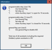
Summary, Cerbo gen auto-start function will OPEN AUX1 on primary and secondary L1 inverters based on a load for a time. This will signal the secondary to turn off AES mode and primary to draw from AC input.
So...
This:
View attachment 180381
Would disable AES on the "backup" inverter when Aux1 is open (should be 1 second, not 10).
This:

On the primary inverter would draw from AC input when Aux1 is open.
The cerbo relay 1 COM/NC would be connected to both inverter AUX1 terminals.
"Backup" inverter(s) would now be powering the load with the primary passing through and ready to engage in powerassist if needed. I think the only lag would be the time the cerbo needs to see the load (as little as 1 second) and the 1 second delay in coming out of AES when AUX1 is closed - so as little as 2 seconds.
Cerbo Gen auto start based on AC load of XW for Y seconds:

Load can be based on:

Attachments
sunshine_eggo
Happy Breffast!
so when configuring them you first create two sets of parallel quattros, and then reboot and go back in to set them to split phase?
No. You would connect all four inverters together via VE.Bus and use VC or the VE.Bus System Configurator to assign each inverter to its position in one session.

VE.Bus System configurator:

Because you can get them confused, you can flash their LED by right clicking:

Click single phase and define Dual phase 180 split phase with L2 fixed:

OK takes you back to here:

You then drag and drop the desired inverters onto the grey box by L1 or L2 Flashing the LED as needed to ensure you're grabbing the correct one. When done, L1 shows the two on L1:

L2:

"Switch as Group" should be UNchecked if you want to possibly ONLY run AC input to one leg and not the other. This allows ONE inverter to sync to a 120VAC input while the other keeps inverting. You can still feed it with split phase.
Then send config, and the inverters are programmed:

Probably a lot easier with VictronConnect:
The YouTube Chanel Andy’s Off grid garage did a video or two on setting them up in series. He had a Multiplus and a Phoenix. The 1st one was on all the time, but when the load spiked the second one would go from pass through to assisting.
Good Luck
Good Luck
The YouTube Chanel Andy’s Off grid garage did a video or two on setting them up in series. He had a Multiplus and a Phoenix. The 1st one was on all the time, but when the load spiked the second one would go from pass through to assisting.
Good Luck
that's an interesting idea as well.The YouTube Chanel Andy’s Off grid garage did a video or two on setting them up in series. He had a Multiplus and a Phoenix. The 1st one was on all the time, but when the load spiked the second one would go from pass through to assisting.
Good Luck
Thanks I think I understand what you are saying here. I will get these wired up on the bench and give it a try. does this prevent me from running AES?No. You would connect all four inverters together via VE.Bus and use VC or the VE.Bus System Configurator to assign each inverter to its position in one session.
View attachment 180404
VE.Bus System configurator:
View attachment 180405
Because you can get them confused, you can flash their LED by right clicking:
View attachment 180407
Click single phase and define Dual phase 180 split phase with L2 fixed:
View attachment 180409
OK takes you back to here:
View attachment 180410
You then drag and drop the desired inverters onto the grey box by L1 or L2 Flashing the LED as needed to ensure you're grabbing the correct one. When done, L1 shows the two on L1:
View attachment 180411
L2:
View attachment 180412
"Switch as Group" should be UNchecked if you want to possibly ONLY run AC input to one leg and not the other. This allows ONE inverter to sync to a 120VAC input while the other keeps inverting. You can still feed it with split phase.
Then send config, and the inverters are programmed:
View attachment 180414
Probably a lot easier with VictronConnect:
sunshine_eggo
Happy Breffast!
Thanks I think I understand what you are saying here. I will get these wired up on the bench and give it a try. does this prevent me from running AES?
AES is only useful if you have periods where you need ZERO power. If you need any power at all, no AES.
Hello all,
Maybe i'm wrong, but i can see an inverter (A : Multiplus 3kVA) as an AC IN of the second one (B Multiplus 5kVA). B is configured to powerassist over 12A and with AES in eco mode.
All electric circuit connected to the AC OUT of B.
When circuit ask for 5A (220V) output, only the A deliver power, it pass through B. At 20A, A deliver 12 and B powerassist for the remaining 8A.
The big advantage is that you save 18W of the idle consumption of B while still being able to have 8kW of power available when needed.
But maybe the Eco mode is not possible in this situation or is too slow to react.
I'm totally of grid and each watt are important.
And i would suppose that parallelizing 2xB (with their 2xA as input) to make a split phase system...would not be a problem.
But i'm no electrician or victron specialist, i'm still a newbie.
RCinFLA
Solar Wizard
- Joined
- Jun 21, 2020
- Messages
- 3,565
I believe AES is like modified sinewave output run through the PWM AC output filter. Victron describes it as 'narrowed' sinewave. It is only in AES mode when enabled and AC output load is low. It goes back to full sinewave when AC loads gets heavier, probably greater than about 50-75 watts range. No need to save idle power when AC load is 7 to 10 times greater
It saves idle power by reducing the PWM chopping frequency gate drive to power MOSFET's. In my opinion, the small amount of idle current savings is not worth having the poor output waveform.
If the AC output waveform is not sinewave, you cannot use it to feed into a second unit AC input.
It saves idle power by reducing the PWM chopping frequency gate drive to power MOSFET's. In my opinion, the small amount of idle current savings is not worth having the poor output waveform.
If the AC output waveform is not sinewave, you cannot use it to feed into a second unit AC input.
Similar threads
- Replies
- 12
- Views
- 1K
- Replies
- 6
- Views
- 422
- Replies
- 44
- Views
- 2K