diy solar

diy solar

Parallel 120v single phase setup for EG4 6500EX - Please check

Yes to Noting Idle Consumption ... on my more recent purchase of my EG4- unit, I noticed there is a power saving mode for night when no ac draw is going on; that appears near 10 -12% of normal inverter idle draw; that looks like .. turns the inverter back on when an AC load reappears. ... some of these setting are fuzzy in my understanding ...until I print out the PDF manual settings page, and write in notes as I configure and experiment ... to understand more .

I don't trust the power saving mode and it seems like pure marketing BS. On paper it looks great but it really does not work.

It doesn't matter ... since the lowest house load I can get to is 80w (modem, router, garage door openers, night lights, etc). Plus the fridge and freezer practically cycles on at least every 20 minutes.

I have thought about running only a critical load but don't want the hassle. I prefer my sanity over making manual or semi automated changes everyday to squeeze and save maybe 1 kwh.
 
I don't trust the power saving mode ... and it seems like pure marketing BS. On paper it looks great but it really does not work.

It doesn't matter ... since the lowest house load I can get to is 80w (modem, router, garage door openers, night lights, etc). Plus the fridge and freezer practically cycles on at least every 20 minutes.

I have thought about running only a critical load but don't want the hassle. I prefer my sanity over making manual or semi automated changes everyday to squeeze and save maybe 1 kwh.
Re: My initial 1st time set up and testing of the EG4 3000 EHV-48; I had an issue with the #4 Setting while setting it up as a Battery Powered Grid BackUp Supply; without Solar In (for now); & with it's internal Grid Powered Battery Charger. My problem was resolved by experimenting; ...this all on my DIY User Defined LiFePO4 Battery Settings. I did notice power savings did reduce the about 0.9 amp idle battery draw to maybe 0.1 amp draw in saving mode, by turning the inverter off. My testing this function with a load draw did see the inverter turn back on when load was applied. BUT ...

... Briefly WOW .. a bit Scary: I had a problem with #4 setting when I changed it from default off to "Savings mode enabled" ... (w no solar IN): ... When AC grid power was supplied to EG4; it did automatically initiate a grid powered battery charge cycle; ... But The Problem (for my unit) was the battery charger then turned off about 3 seconds later, and then cycled on again, and off again ... like that while 120vac grid supplied power to the EG4 with the "Savings Mode Enabled"

... THE FIX for me to Grid powered Battery Charger cycling off and on ... was switching my # 4 setting back to its' default "Savings mode disabled". AND: (not sure if this was essential to my fix, but likely was) ... I then went into User Defined Setting # 32; and changed Bulk charging time (C.V. stage) ... from its' "Automatically (Default) to 15 mins (looks like 5 - 900 minute options) Then Grid Powered Battery Charging returned to normal (again on user defined/ not rack battery w protocol cables, and no solar in). I was indeed happy to figure that out. ... and think an eventual firmware update would be a good idea for EG4 ...

P.S. to more fully understand how these All In Ones work with those numerous setting options: I print out the settings part of their pdf manual, and write notes on that as I set em up and test to see how the settings work. My notes are the source of this report. I Love seeing the evolution of All In One options, and think the EV4 options represent (in my personal opinion) being head of pack in some ways, with a firmware update for this issue someday due.
 
Last edited:
Please
I am still setting up and installing the system so it’s messy.


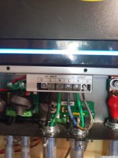
Pictures are meant to show Inverter Port A and B for each inverter.

The HS host and SL slave inverter does not matter. If both inverters were shut down, the inverter that starts up first is the HS inverter. I labeled them Left and Right so you can tell them apart.
Please help me I have so error code

I try to do exactly the same I mean 120vsingle phase (No NEED split phase)
 
Please

Please help me I have so error code

I try to do exactly the same I mean 120vsingle phase (No NEED split phase)
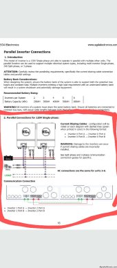
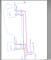
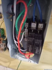
I have a 120v critical electric panel / load center with a 60A breaker taking up 2 slots. I connect Inverter 1 to the left slot, Inverter 2 to the right breaker slot, and a 6awg jumper wire between the left and right breaker slot. (Please see the picture)

Everything is working fine until I add an input AC.

But I have to tell you

Each neutral (AC input neutral and AC output neural) are connected together on both inverters

The are the same phase AC input (Generator SDMO 60KiloWatts)

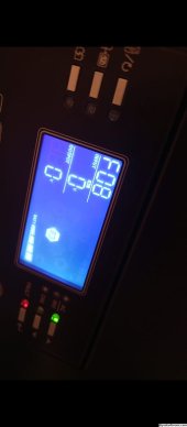
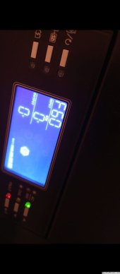
when I try to transfer on generator, I have a warning code 10 after one of the inverters gets an error code F08 then F60. and shut down


but without the AC input everything works perfectly as you can see in the video


Please can you help and tell me what I did wrong?

I also attach when I got the error code


Thank you in advance
 

Attachments

  • WhatsApp Image 2023-10-09 at 20.02.05.jpeg
    WhatsApp Image 2023-10-09 at 20.02.05.jpeg
    325.7 KB · Views: 8
  • WhatsApp Image 2023-10-09 at 20.02.06.jpeg
    WhatsApp Image 2023-10-09 at 20.02.06.jpeg
    352.2 KB · Views: 8
  • WhatsApp Image 2023-10-10 at 12.06.02.jpeg
    WhatsApp Image 2023-10-10 at 12.06.02.jpeg
    241.5 KB · Views: 8
  • diagram.PNG
    diagram.PNG
    191.4 KB · Views: 8
  • WhatsApp Image 2023-10-10 at 11.11.42.jpeg
    WhatsApp Image 2023-10-10 at 11.11.42.jpeg
    269.1 KB · Views: 8
  • WhatsApp Image 2023-10-10 at 12.46.48 (2).jpeg
    WhatsApp Image 2023-10-10 at 12.46.48 (2).jpeg
    104.9 KB · Views: 8
  • WhatsApp Image 2023-10-10 at 12.46.48 (1).jpeg
    WhatsApp Image 2023-10-10 at 12.46.48 (1).jpeg
    196.7 KB · Views: 5
  • WhatsApp Image 2023-10-10 at 12.46.48.jpeg
    WhatsApp Image 2023-10-10 at 12.46.48.jpeg
    202.1 KB · Views: 7
I am no expert. Please proceed your own risk.


I didn't have my inverters in parallel for more than a couple of days. I didn't need 13kw. Never hooked up AC input to them when in parallel.


I would try to simplify the setup

1. Both inverters work in parallel single phase. Check!
2. Try one inverter only with AC input.
3. Try the second inverter only with AC input.


Once everything works independently.

I would check your neutral to ground bond first. Seems like you have the bond where your 50a breakers are located.

Please explain your wire colors. What is green, white, red, blue.

I see you using green for neutral, blue for line, black for ground, black for line. It is a bit confusing.

For your drawing, I like to see every wire as it should be wired. I don't see the ground for AC input, neutral for AC out, ground for AC. While I can guess where they are, best to represent everything as it should be to minimize any confusion. Makes it more difficult when troubleshooting.

What comes after your 50A breakers?
 
Those fault codes are not really helpful.

Do you have Solar Assistant or watch power setup so you can read settings from the inverter?
 
Back
Top