Dinobot248
New Member
Before I actually connect my second EG4 6500EX in parallel for single phase 120v, I wanted to check by understanding. Better to ask before I make a mistake. Please advise and thanks in advance.
EG4 6500EX settings
Below are the notable settings and/or changes. All other settings for both inverters will be setup in the same way. Firmware is the same on both. Battery cable is setup.
Inverter 1
05 = EG4, for closed loop communication with LifePower4 rack of 6 batteries.
28 = PAL, for parallel
Inverter 2
05 = USE, for user defined with LifePower4 rack of 6 batteries
26 = 56.4 V, default value for bulk charging voltage
27 = 54.0 V, default value for floating charging voltage
29 = 44.0 V, default value for user defined battery
28 = PAL, for parallel
Questions / Comments.
- Are the default battery charging voltages (26, 27,29) good or should they be changed?
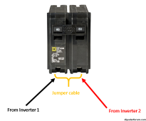
- I have a 120v critical electric panel / load center with a 60A breaker taking up 2 slots. I plan on connecting Inverter 1 to the left slot, Inverter 2 to the right breaker slot, and a 6awg jumper wire between the left and right breaker slot. Its probably not formally correct, but is correct enough? Please see the picture.
- In case anyone is wondering, I"m not ready for split phase 240v. Just trying to test the second inverter for a week or two before I make more changes.