Forum Guru ? Ohhh my, been called many things (I have an Ex so no imagination required, eh.) but Forum Guru ? That's New.
2x174 & 2x 280.
YES, the 174's cutoff for LVD before the 280's.
The 280's keep pumping out the juice even with the 174's disconnected.
Once LVD, they do not suck juice out of the 280's, only when they pulse "ON" but without real charge coming they go back to LVD.
I have a shunt on each pack, as well as a "master" shunt for whole system view. I can & do watch them.
I just completed a 3 week THRASH TEST on the packs and really beat on them with Low to High Amp changing & Discharging and with handicapping (packs off and doing only 1 pack or 2 at a time) and various combinations for stress testing to see what exactly they will do and how. I did NOT document that long, tedious and outrageously expensive set of tests... I am offgrid and have to run a Big Genset for forced hard charging and it is a PIG to be polite about it, I dropped an obscene amount of cash into it's tank + 5 oil changes (synthetic only).
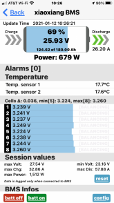
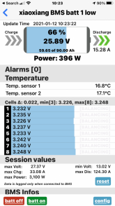
BMS !
The devil is in the details... I run with Chargery BMS8T's each with a 300A DCC (Solid State Smart Relay) and that affords me the ability to closely observe & monitor the situation with the packs in the bank. The majority of BMS' when they reach LVD or HVD will cutoff as they should for the condition. They will "pulse" open or ON momentarily to test to see if there is an incoming charge for LVD situation or if there is a draw on an HVD condition and if so, goto ON state and accept the charge or do discharge. Every BMS is slightly different depending on the programming in it and the hardware it uses.
HEADS UP !
When dealing with multiple packs in a bank, things get complicated and quickly. You CANNOT read "End-Amps" or calculate such with multiple packs in place. You CANNOT have any single BMS tell an Inverter to "stop inverting" because it does not know the state of the other battery packs in the bank. The same applies to Charging as well... This also applies to the Solar Charge Controller as well...
If you are contemplating a larger bank with 4+ battery packs, then a different kind of BMS is required, one which has a centralised monitoring & control system that can be the "arbitrator" between devices and the battery assemblies. Alternately, using BMS' which can communicate / interact with a PC or Raspberry Pi which can then be programmed to read / monitor battery packs and issue instructions to Devices like an Inverter/Charger/SCC using CanBus, Modbus or other is another route.
Hope it helps. Good Luck.