diy solar

diy solar

Paralleling LFP cells at rest to "balance" them

snoobler

Solar Honey Badger
Joined
Jul 10, 2020
Messages
8,387
Location
HBR, AZ
Hypothesis: Paralleling cells at rest does almost nothing beneficial. While voltages may be equalized, their states of charge remain dramatically far apart.

I decided to do an experiment.

Take two CALB 40Ah LFP cells.
  1. Fully charge to 3.65V
  2. Fully discharge to 2.5V
  3. Charge ONE to 3.65V
  4. Let them sit for 12+ hours
  5. Put them in parallel
  6. Let them sit in parallel for X hours
  7. Discharge each to measure how much charge transferred.

I am on #6 with X currently at about 2 hours.

There are some limitations. These cells have been abused in a Gen2 Prius aftermarket plug-in hybrid kit with no cooling and have been discharged to 0.6V each. My equipment is not ideal for these lower voltage cells, so I'm getting a bit of voltage drop. The charge should be pretty good with a 2A termination, but the discharge is terminated somewhat prematurely. There's not much left between 2.7 and 2.5.

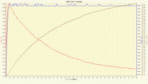
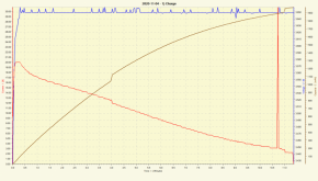
Step 1, 20A charge to 3.65V, taper to 2A, terminate:

Cell #1:
1604624512670.png
About 1.9Ah in.

Cell 2:
1604624594612.png
About 0.65Ah in

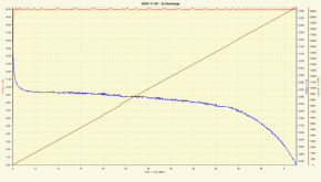
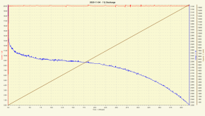
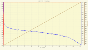
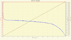
Step 2: 20A to 2.5V:

Cell 1:
1604624684847.png
21.3Ah

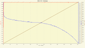
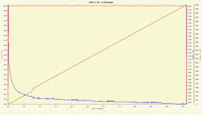
Cell 2:
Had some "Oops" where the unit turned off early, so you have to imagine these are continuous:
1604624861081.png
1604624902172.png
23.3Ah

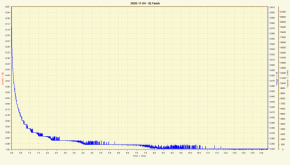
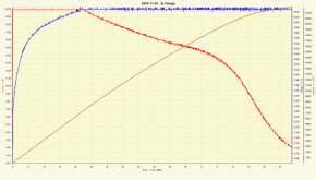
Step 3: (same charge as step 1, cell 2 only)
1604625372192.png
22.4Ah in

Step 4:

Cell 1 (sit for about 16 hours):
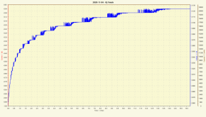
1604625510025.png
Bounced to 3.124

Cell 2:
1604625599816.png
Ended at 3.34

I put them in parallel:
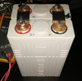
1604625751164.png

Any suggestions on duration? I reserve the right to ignore you, but I'm shooting for about 24 hours.
 
23 hours.

I'm going to call my hypothesis mostly disproven because of it's aggressive phrasing.

Hypothesis: Paralleling cells at rest does almost nothing beneficial. While voltages may be equalized, their states of charge remain dramatically far apart.

Revised to:

Hypothesis: Paralleling cells at rest is not an effective means of balancing cells. While voltages may be equalized, their states of charge do not balance to an acceptable degree.

Cell 1 had 9.3Ah and Cell 2 had 14Ah. That's substantially more than I've found on NiMH chemistry.

0% SoC went to 42.3% SoC
100% SoC went to 64% SoC

These are still miles apart in terms of balance, but they moved way more than I expected.

Since as-received new cells are likely closer than this 22% SoC discrepancy, I'm going to re-charge each to input the same charge, 9.3Ah and 14Ah, respectively, rejoin them and check them in a number of days to see how much charge has transferred.

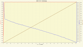
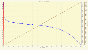
Here are the discharge curves:

Cell 1:
1604711523150.png

Cell 2:
1604711577644.png

Yes, they look nearly the same, but Cell 2 went for over 40 minutes vs. about 28 minutes.
 
Good experiment, thanks for sharing.

Quite a few people i know have put packs together without top balancing - then set the SCC at 3.5V/cell and used active balancing.

It will be interesting to see how they fare long term, but i haven’t seen any initial problems.
 
So, they're just short charging to 3.5V/cell during their cycling? I would conclude from your statement that passive paralleling them permits normal operation at up to 3.5V/cell?

Active balancing? With active transfer balancers or passive (resistor burn-off)?

I will probably let them go for a week. This is on the scale of the 4+ days it takes to top balance 8X 280Ah cells in parallel @ 10A.
 
No paralleling of cells at all before use, just assemble series pack, add active (transfer balancer) and limit maximum charge voltage to 3.5V/cell.
 
Results are in.

Cells were paralleled for 7 days and 14 hours and sat for about 36 hours disconnected before they were tested.

The cells remain separated by almost 2 Ah. This is approximately 10% of the capacity of the cells, which is a mile in the context of "balance."

Cell 1 (11.5Ah total):
1605504967126.png
Forgot to remove the 9300mAh limit, so continued discharge:
1605505003578.png

Cell 2 (13.4Ah):
1605505135903.png

So if your goal is to "balance" your cells by wiring them in parallel and letting them sit, it's not likely that you'll achieve anything meaningful.
 
Last edited:
So based on what you observed, if you put the cells in parallel, discharged to....say 2.5v, charged to 3.6v would they then be "balanced"?
 
Yes, but a repeat charge to 3.6 should be all that's necessary. The current flow will pass almost exclusively into the lower SoC battery due to microvolt difference between the fully charged battery and less than fully charged battery. At 10A on 280Ah of capacity with only a 10% variation, it should only take a few hours.
 
I still don't get it. The suggestion here is that there will be some intercourse between the paralleled cells, but not very significant. Why should there be any interaction between them if no charge or load is applied to the terminals? I might expect a slow degradation of SoC independently that might be interpreted as a result of interaction, but that would be incidental / coincidental to the observation. I believe that in this situation there is NO interaction of equalizing/balancing whatsoever. Yet this discussion seems to imply that there is, but in a limited way. Please explain.
 
The Sun rises in the east and sets in the west. Current flows from high voltage to low.

What does that have to do with it? If two cells are placed in parallel with nothing else connected to them, what exactly accomodates the flow from high voltage to low between them? Osmosis?
 
The Sun rises in the east and sets in the west. Current flows from high voltage to low.

What does that have to do with it? If two cells are placed in parallel with nothing else connected to them, what exactly accomodates the flow from high voltage to low between them? Osmosis?

Well .... I guess you need to study the basics of electronics and current flow. The difference of voltage potential is what causes the current flow.
How do you think a charger charges a battery?
 
The Sun rises in the east and sets in the west. Current flows from high voltage to low.

What does that have to do with it? If two cells are placed in parallel with nothing else connected to them, what exactly accomodates the flow from high voltage to low between them? Osmosis?

In this scenario 0% SoC cell was lower voltage than 100% SoC. When they were placed in parallel, there was a current flow between them according to I = V / R where V is the voltage difference and R is the internal resistance of the cells.

The initial current was likely pretty large, and the voltage difference between the two cells became very small, and a small amount of current continued to flow between them. This allowed the two to be within 22% SoC of each other after 23 hours.

The test was repeated and they were connected for 7 days and 14 hours. Over that time, enough capacity was transferred between the cells to bring them within 10% of each other.
 
I am a licenced amatuer radio operator since about 1990 - Coded Technician class (callsign N2MZN). I am a retired computer engineer, Comptia A+ Certified. I am college educated. Big deal. But I surely know the basics and what is obvious. What intrigues me is whatever the principle is that transfers SoC between physically connected cells in parallel without some external path between their common positive and negative poles.

How does that work without intervention of an external device like a BMS or power supply to create a load or charge that would carry electrons between the cells to balance their SoC ?

Am I not making myself understood?

The process of the sun rising and setting is a function of the earth revolving. If it didn't, it wouldn't happen - unless you are a flat-lander ...

The process of current passing from high to low involves a path. Where is the path in this case? It is not in any connection that I can see, just because they are wired in parallel. Help me conquer my ignorance about that. What don't I know?
 
I don't understand why you can't see that wired in parallel ....is the path. Maybe it's Saturday night and there have been too many adult beverages.

Current will flow from a higher voltage potential to a lower voltage potential when connected by something that has conductivity.
 
I guess we have to agree to disagree. I can't understand where there is a handshake between the cells that way. Not unless there is some kind of leak.

I don't drink. I have had this question all day.

So, i am not drunk or on medication. I am just ignorant?
 
I don't know any other way to explain it .... If you connect a higher voltage potential to a lower voltage potential with a conductive object ..... current will flow til there is no longer a difference of voltage potential.

I'm outa here .... gotta get up early.
 
Oh cool - we are playing this game in multiple threads :)

For a graphic demonstration, connect a discharged supercap in parallel with a battery of your choice. The spark will show you where the current path is.

The confusion i believe you are encountering is caused by LiFePO4 having such a flat voltage curve that it’s possible for 2 cells to have very different states of charge, but exactly the same voltage. These cells connected in parallel will not balance.

If there is a difference in voltage, current will flow through the connection between the poles (the spark you saw with the supercap). If there is no difference in voltage, there is no current flow between cells.

The real kicker with LiFePO4 is that if you have an external voltage source connected at a high knee voltage the cell can still absorb current without increasing voltage as lithium plating occurs.
 
Back
Top