diy solar

diy solar

Portable Victron Power Station operational

Here is a link to the specs for the new version of JK with Inverter Support. They have built-in precharge and current limiting +.
Just highlight the model and select it, then scroll down to see the different specs.

BTW, My current packs all have JKBMS (previous version) and no precharge, but with 6 packs online, the capacitor demand isn't an issue...
It says it supports parallel connection, does that mean the BMS can communicate with another Battery BMS and sync?

Also, can this BMS be used as a regular BMS without the use of the Inverter communication feature?

Thanks.
 
It says it supports parallel connection, does that mean the BMS can communicate with another Battery BMS and sync?

Also, can this BMS be used as a regular BMS without the use of the Inverter communication feature?

Thanks.
yes on both counts BUT the folks at HankZor (the usuals who deal with JK) have gone a bit dumb "again" and JiKong itself is not terribly helpful either. None of which is a good thing IMO. There are issues presently with the latest models so I am holding my shipment till December by which time the issues should be resolved. Fortunately I have other avenues of information but those are behind NDA's so I can't get into it.
 
yes on both counts BUT the folks at HankZor (the usuals who deal with JK) have gone a bit dumb "again" and JiKong itself is not terribly helpful either. None of which is a good thing IMO. There are issues presently with the latest models so I am holding my shipment till December by which time the issues should be resolved. Fortunately I have other avenues of information but those are behind NDA's so I can't get into it.
Wow!
I had an impression JK probably had the best BMS back when I was looking for my first one but dang, with this, they'll be in their own league as long they make it work. Kudos.

Let's wait and see, very exciting.

Thanks for the info, Much obliged.
 
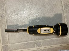
Well I had a chance to borrow my mechanics high end torque wrench. Sadly its lowest setting was above 6 nm. Considering the stories of snapped screws on battery cells I elected to use a torque screwdriver that has been recommended by others. It is not digital but has a fairly easy scale for adjustments. I really liked that it came with a 1/4 to socket adapter. This made tightening up the screws on the terminals much easier. I went shy of 6 nm. They are still quite snug and should be fine.

IMG_3187.jpeg
 
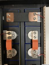
On another thread it was recommended to place a non corrosive coating on the copper bus bar. I searched the site and this appears to be a consideration in marine or higher humidity areas. Most of the time this unit will be in a climate controlled area. Since there is an opportunity that it could be used outdoors I did place a very fine film of No-Ox-ID on the side facing the terminal. Recommendations from others are to use a very fine film and to stay away from the screws since this can affect torque settings.

IMG_3189.jpeg
 
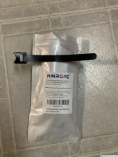
Anyone who has been on this journey can understand this. One tends to pick up little odds and ends that can be helpful from time to time. I found these a while back while working on something else. They are velcro based zip ties. They are a little wider so should be gentle enough to help secure and organize the BMS wires that always seem to be "hanging around" after a build. I elect not to trim mine since I personally like to keep them the same length.

IMG_3190.jpeg
 
Anyone who has been on this journey can understand this. One tends to pick up little odds and ends that can be helpful from time to time. I found these a while back while working on something else. They are velcro based zip ties. They are a little wider so should be gentle enough to help secure and organize the BMS wires that always seem to be "hanging around" after a build. I elect not to trim mine since I personally like to keep them the same length.

View attachment 181077
Those are nice for systems that are reconfigured often.
I've used them a few times.
 
Small update. Got Bms ready. Was a delay because the battery lugs were the narrower instead of wide lugs. Wanted a better contact area with the battery.
 
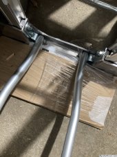
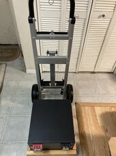
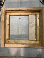
There has been a lot of discussion on battery orientation. Currently I will be positioning my batteries upright. The neat thing about this hand truck is that it has a tongue which extends out to hold larger items. After I did my measurements I realized that it would be extending out an additional 10 inches which really isn't needed. As I looked at it more I realized that there are two bolts which hold the hinge bracket. Doing some quick measurements I realized that 2 inch angle should allow me to connect a holding case to these bolts. This has been placed on order. I selected aluminum extracted 6061-T6. According to one source it has a yield strength of 35,000 psi and shear strength of 30,000 psi which may not exactly apply to what I selected, however unless I'm mistaken should be more than adequate while helping to keep things lighter. I am looking at constructing a holding case. The back wall attached to the angle is currently slated to be a 2x6. I debated the side wall materials. A 2x6 would allow better lateral support. An online calculator suggested that making the two side panels out of 2x6 vs 2x4 would add about 2.5 lbs. I am considering 1.5 angle along the bottom edges of both side 2x6s although I might decide to utilize a 2x2 instead. Either would add additional support and hold the 3/4 plywood currently slated for the floor of the box. Again, this is still a work in process so the design concept is still subject to change. Most of these materials are already on hand from other projects. Can't tell you how many variations have already been considered. I want to place padding between the battery case and the wooded box. I still have the packing foam which originally came with the batteries and battery case. This is the top consideration. A second material considered was foam pipe insulation such as provided at the big box stores.

IMG_3196.jpeg
 
Last edited:
Keep It Sweet & Simple
Wise advice indeed. I much admit, I found myself playing with need to have versus want to have. This morning I reviewed the setting where this is to be installed. I still plan on pursuing Victron for redundancy as indicated above, however I will be scaling back on some of the things I was considering due to space.

Have decided on a box configuration. It will be simple in nature and I have most of the materials already. Hope to provide some updated photos in the next week or two. Busy schedule ahead.
 
Here are two photos showing the battery attached. The first photo shows the metal bracket attached to the carrying box. The second shows the battery in the box.

IMG_3438.jpeg

IMG_3439.jpeg
 
Last edited:
Did you order your multi 2 yet? Current Connected mentioned in a post the other day that there's a price cut on them and the quattros, around ~$100-$200 on the smaller 3-5kVA units.
 
Ordering the Multiplus II from Current Connected is next on the list. Moving forward as budget allows
 
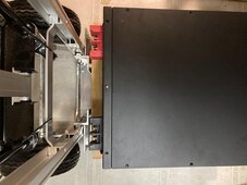
It made sense to move the battery terminals closer to the dolly so I wouldn't need to string wires over the top of the battery case. To help with this I reinforced the underside of the battery box. I am also considering side supports and have picked up some high strength stainless steel cable that I am considering stringing between the dolly frame and the end of the battery box:

1705177799407.jpeg
 
Last edited:
@timselectric and @HighTechLab helped me understand that when the Multiplus II is not attached to an AC source that it bonds neutral and ground. It was recommended that I bond the battery box and Multiplus II to the dolly frame. This photo shows the bonding screw I am hoping to use plus the updated alignment of the battery. I removed the handles because they were not needed here:

1705177985666.jpeg
 
I'm concerned that the battery terminals line perfectly up with the dolly frame.
Looks like an accident waiting to happen.
 
Back
Top