diy solar

diy solar

Pre-charging inverter capacitors with a lead pencil?

Boondocker

New Member
Joined
Feb 1, 2021
Messages
20
I was told by the guy at Watts 25/7 Growatt dealer that I could pre-charge my inverter capacitors with a lead pencil as my resistor, anyone ever heard of this?
 
Sort of MacGyver solution but it is possible if nothing else is available and you are stuck in middle of Alaska.
it will get really hot and in some cases explodes if you heat the pencil too quickly.
 
I was told by the guy at Watts 25/7 Growatt dealer that I could pre-charge my inverter capacitors with a lead pencil as my resistor, anyone ever heard of this?
The benefit being what, a solution on the fly?

Most of us want a precharge solution set up with instructions so that anyone not ‘in the know’ could power-up the system.

Totally turn-key and fail safe are the objectives in that case.

Telling someone to find a pencil and hold it against this and that for so many seconds/minutes before turning on the switch sounds like a recipe for a mishap (though if you’ve fried you power resistor and are desperate for a way to tear your system without causing a spark, sounds like it’s a promising back-up plan ;)).
Yeah, I'm gong to get a proper resister and know it's being done right. In Will Prowse's video, he uses the negative terminal but in other videos, I've seen they use the positive, can I assume that it doesn't matter? Also, Will doesn't say if the inverter is turned on or off while he's doing this, do you happen to know?
 
The graphite in a pencil is conductive.. Very easy to set the pencil on fire by connecting pos and neg of a 12 volt battery.. takes just a few seconds and yo have an instant camp fire starter.

Because of the low resistance, I don't think I would attempt this with a 24 or 48 volt system as the pencil could blow up in your hand.

Best to just use an incandescent light bulb.. 60 or 100 watts would work well.
 
Yeah, I'm gong to get a proper resister and know it's being done right. In Will Prowse's video, he uses the negative terminal but in other videos, I've seen they use the positive, can I assume that it doesn't matter? Also, Will doesn't say if the inverter is turned on or off while he's doing this, do you happen to know?
I just got a 2-way switch (connected to the + terminal) and wired input ‘1’ to the battery input (‘2’) through a power resistor.

I suppose you could leave the inverter ON - it won’t start as long as the capacitors have not charged.

But the issue I see is that if the inverter starts drawing power while you’re still connected through a power transistor, it going to immediately turn off (and at least partially drain the capacitors in the process…).

I suppose over 90% of the charge is between 0V and the LVD voltage of an inverter, so maybe it’s not an issue…
 
I like the light bulb idea, bulb will glow until the caps are charged, now hit the on switch.
But don't know if it will have enough conductivity to charge the capacitors quickly enough.
 
What's the best resistor for pre-charging my inverter when connecting it to the battery bank; 400ah at 24VDC, 100ohms, or bigger?
Depends on the amount of capacitance your inverter has and how it boots up and if it is turned on.
In other words, 100 or 10 might work, pencil does too but to do it properly and safely....
 
Many auto parts stores carry a resistor to use with led lights so the turn signals blink correctly.
I use a 40w light bulb. It works great, and it does dimly glow for a few seconds as it charges the caps.
 
I've been suggesting a coil of Romex (or other wire, 12 awg or so).
Connect white and black at one end with wire nut. Use the length of wire as a resistor. Look up ohms/foot in a table.
For a 50V system, 0.5 ohm of wire would allow 100A to flow initially. If inverter turned on and drew 10A (500W load), then 5V drop would remain, 45V to feed inverter. If no AC loads are present, current draw and voltage drop should be about 1/10th that much (~ 50W no-load, 1A draw, 0.5V drop.)

Edit: This assumes you connect the resistor with a switch/relay capable of closing on 100A draw, not just carrying 100A when closed. Momentary 100A, so not as much heating as continuous operation. But contact bounce does mean 100A arc, can then weld. (not nearly as bad as say 2000A inrush and bouncing). A higher value resistor avoids this. Using two copies of your expensive high-current BMS relay should be OK at 100A.

Something in the 0.1 to 1.0 ohm range should work.
Reason for length of wire, not discrete resistor, is that it can easily tolerate the surge of power dissipated in it, both the pulse when precharging capacitor and the steady dissipation feeding inverter. Time to close switch after precharge isn't critical.
If inverter draws current, resistor would heat up very fast, also cause excessive voltage drop.

Resistor or lightbulb will work fine so long as inverter draw is near zero. If you find voltage across it doesn't drop low enough because inverter turns on quickly, then my wire suggestion could be considered.

Typical inverter might be 0.1F capacitance. That's 0.1 amp seconds per volt, 5 amp-seconds for 50V. If 100A delivered continuously, would charge in 1/20th second. But this is an RC delay, T = RC = 0.5 x 0.1 = 0.05 seconds to reach (1 - 1/e) or about (1 - 2/3) = 1/3 of final voltage. By 10 time constants, 10 x 0.05 = 0.5 seconds, (1 - 2^10/3^10) = 0.017 remaining (98.3% of the way charged)
 
Last edited:
What's the best resistor for pre-charging my inverter when connecting it to the battery bank; 400ah at 24VDC, 100ohms, or bigger?
See:


Along with showing how to setup a disconnect switch with the pre-charge resistor, it has some info on what resistor to use for various voltage systems.
 
i suggest not using pencil resistor due to Resistance Too Low (depends) and fire risk from low thermal mass, poor heat transfer

curious about this and did some research, check out this article,

Pencil Resistors and their working​


for understand pencil resistor

in an emergency, yes, but Measure Ohm of pencil resistor and calculate the Expected Amp/power flow Given System Voltage and understand the max power dissipation of the pencil first
 
I've used a 10 ohm 50W resistor on both a 4S pack and a 8S pack. I experimented first to see if it did the trick. No arc when touching the resistor across the connection between the battery and the inverter. On the 8S pack I only touched it for a bit less than a second, then touched the lug directly with the ring terminal. No arc. Anyway, I'm happy with the 10 ohm resistor.

I ended up buying the same Perko switch that @FilterGuy wrote about in the afore mentioned resource (accidentally, since I bought it before I saw the paper!), and was able to print and use the nice label he did for the switch.
 
What's the best resistor for pre-charging my inverter when connecting it to the battery bank; 400ah at 24VDC, 100ohms, or bigger?
hi!!

to calculate how many amp expected at first,

divide System Volts by Resistor Ohms to estimate Amps

then multiply Expected Amps by System Voltage to get Power

24VDC implies 8S and I assume LiFePO4 so max 3.65*8= 29.2 Volts Peak System Voltage figure (it will usually be lower but higher voltage with same resistor means more power and heat so it helps to size the resistor)

29.2 Volts / 10 Ohm = 2.92 Amp

another mentioned that 10 Ohm Resistor work decent with their 4S,8S LiFePO4 bank to as you say prevent the spark

recommendation?

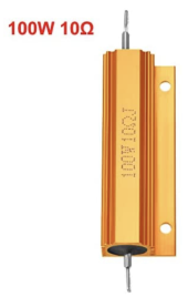
i suggest try it with search "100W wirewound resistor X ohm" where X Is the ohm you choose. i suggest 10-50 ohm for 24V system (always calculate expected amps and powrr though!)

https://www.amazon.com/uxcell-Aluminum-Wirewound-Replacement-Converter/dp/B07KP9JHF4/

1642435286482.png

uxcell has supplied me with 100W wirewound resistors and they have so far tested very close to label Ohm value and feel solid.

100W might sound excessive but that just means it will not heat up as much and as a result be less of a fire risk.

closing up..

your system voltage. 24 (29.2 absolute max)

Volt / Ohm = Ampere
24V/10 Ohm=2.4 Ampere
24V*2.4 Ampere ≈ 57 W

29.2V/10 Ohm=2.9 Ampere
29.2V*2.9 Ampere ≈ 85 W

for 100W resistor i like to keep it down to 25% of Watt rating to keep things chill and low fire risk since im having a computer connect it, not manual use. so that means i would treat a 100W wirewound resistor with 25W only

Ohm = (Volt*Volt)/Watt

(24*24)/25=23Ohm resistor to get 25Watt with 24V system

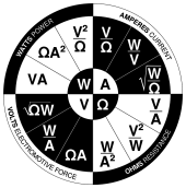
i used this picture repeatedly to help keep units straight

good luck

1642435086741.png
 
I was told by the guy at Watts 25/7 Growatt dealer that I could pre-charge my inverter capacitors with a lead pencil as my resistor, anyone ever heard of this?
I have used an INCANDESCENT 75 watt light bulb to avoid sparking on initial charging of capacitors in my inverter. Light bulb connected in series with battery: either + or- side. I use + side because I’ve got - tied together and grounded( solar input-, inverter- and battery -). Regardless, insert the bulb in the circiut (disconnect 1 battery wire from inverter, connect light bulbs 2 wires , 1 to battery 1 to inverter)
When bulb quits glowing ( a few seconds) remove bulb and reconnect wire to inverter. No need to rush the reconnection: capacitors should hold charge for a relatively long time. Do not try this with an LED light bulb. Old school incandescent bulb only. Pencils have better uses and offer a fairly small resistance unless using fine pencil lead. That was something like one of Edison’s original lamp filaments trials. It glowed before burning out.
 
given System Voltage and Resistor Ohms, how to calculate how much Watts precharge?

first, calculate Precharge Amps by dividing Volts by Ohms.

Volt / Ohm = Amp

calculate Precharge Power by multiplying that Amps by System Voltage.

Amp * Volt = Watt
 
The one @curiouscarbon showed is the exact resistor I used.

Also keep in mind that the wattage rating doesn't mean too much. The max power will be simply Volts*Volts/Amps, but that will only pass through the resistor for a fraction of a second. I'm only guessing, but if the math says it will peak at 100W, you could easily get by with a 50W resistor.

Having said that, I am not a lawyer or doctor, and I don't have a PhD in pre-charge!
 
Back
Top