diy solar

diy solar

Problems with Eg4 6500ex buyer beware.

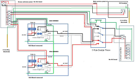
I have an acreage and have 4 buildings on it. Meter socket is at the utility pole and that is where the main disconnect is located with a main service panel. Each building has a feeder from the main service panel. House is 90 feet from pole, shop is 120 feet, cold storage is 80 feet behind the shop and another small storage shed is 5 feet from the main service panel.

This is how all acreages and farms are wired in this area. It is a good setup, the N-G bond is located close to the utility transformer which would be source. When you add another source, it changes things if it is not close to the N-G bond.
It shouldn't change anything.
The breakers in the furthest (from the N/G bond) sub panel still open on a fault. The fault current path length doesn't change by moving the source.
 
It shouldn't change anything.
The breakers in the furthest (from the N/G bond) sub panel still open on a fault. The fault current path length doesn't change by moving the source.
This isn't about ground fault clearing.

It is about zero voltage reference. With the N-G bond 90 feet from source such as my house to the pole, that is a total of 180 feet of wire. There is impedance.

My guess is the inverters use the neutral to zero voltage reference to base output voltage.

I ran across this article on Fluke's website some time ago. While it discusses grounding separately derived systems, the rules still apply when using any transformer, which an inverter is a transformer. The following paragraphs shed some light on the subject of proper grounding of any transformer.

Grounding and bonding

Grounding means connecting something to the earth. Bonding means connecting objects together. A separately derived system must be grounded to earth at the source. All non-current-carrying metal parts and equipment must be bonded to the grounding point of the derived system. Bonding of metal equipment provides an effective ground-fault current path to ensure that the electrical system is safe from the potential for electric shock and fires. Proper grounding of separately derived systems stabilizes phase-to-ground voltage. NEC Article 250 in general and 250-26 in particular address the grounding requirements of a separately derived system.

Proper transformer grounding is critical. Making a grounding connection - typically to building steel, which is required to be bonded to all cold-water pipes - establishes a ground reference. Make proper bonding connections by exothermic weld, not clamps that can loosen over time. Ensure that the high-frequency impedance of the grounding electrode conductor is as low as possible. Wide, flat conductors have less inductive reactance at higher frequencies, and are preferred to round conductors for that reason. The distance between the neutral-ground (N-G) bond at the transformer and the grounding electrode should be as short as possible.

The neutral and ground must be connected to the transformer neutral bus. Making the N-G bond at the main panel is not advised in order to segregate normal return currents from ground currents. The transformer neutral bus is the only point on the system where the neutral and ground should be bonded.


A few thing should be noted:
1- Proper transformer grounding is critical.
This applies to any transformer that is source.
2-The distance between the neutral-ground (N-G) bond at the transformer and the grounding electrode should be as short as possible.
The reason is impedance of the circuits involved.
3-The neutral and ground must be connected to the transformer neutral bus.
Is the utility transformer grounded at the transformer neutral bus? It certainly is or ground fault clearing would not work.

4- Making the N-G bond at the main panel is not advised in order to segregate normal return currents from ground currents. The transformer neutral bus is the only point on the system where the neutral and ground should be bonded.

I find this rule interesting,it certainly shows that bonding should be at the source, whether it is a utility transformer or a transformer on a separately derived system or even an inverter transformer. All are source and as such bonding should take place at the source.

This is why the 6500EX can not regulate output voltage correctly. This is why the LV6548 with an internal bond can.

Violate any of those 4 points and the result is what you see with the 6500EX. It is also why I saw the led light glowing with the switch off. Current is traveling any where it can find a path to get back to source.
 
On a side note (perhaps you already done so), have you done any research into LED bulbs which may advertise as flicker free?


(please pardon me if it was already discussed in this thread before, in case I didn't see a previous post)
One point, the lights don't flicker with the LV6548 but do with the 6500EX. Output voltage fluctuates on the 6500EX but doesn't on the LV6548.

Is it the light or the inverter?
 
In your case, you almost need to be able to dynamically change the bond location depending on Grid vs inverter operating. Not sure how you'd do that. These inverters apparently need to be right next to the main bond location so as to avoid this issue.
 
In your case, you almost need to be able to dynamically change the bond location depending on Grid vs inverter operating. Not sure how you'd do that. These inverters apparently need to be right next to the main bond location so as to avoid this issue.
I brought this up in this video.
 
Current is traveling any where it can find a path to get back to source.
And the connection that is providing that path needs to be corrected. This is a wiring issue that requires troubleshooting.
 
I can't imagine why they would do that.
As they can work in a floating system.
Only if there is a N-G bond at the inverter or a short distance from a N-G bond such as a RV.

The 6500EX is basically floating with the impedance of the circuit to the N-G bond when 180 feet of wire is involved. You can see in the videos how that worked out, i.e, glowing led light with the switch off.
 
One point, the lights don't flicker with the LV6548 but do with the 6500EX. Output voltage fluctuates on the 6500EX but doesn't on the LV6548.

Is it the light or the inverter?

I totally agree the inverter model is introducing the bug (I read your previous posts about the LV6548s not having the issue), but there are some bulbs out there that can take a wide range of AC voltage (like maybe 90-140v), rectify to DC, switch through PWM, whatever, clean up / filter it to make an even smooth DC bus (no matter if the input voltage is fluctuating) to drive the LED without having a visible flicker...

Like I was meaning, sure, we want to get to the root cause if possible, but if it proves to be very difficult or expensive to remedy, then perhaps a workaround of getting some different LED bulbs could be a reasonable alternative in the meantime (to help improve WAF).
 
Only if there is a N-G bond at the inverter or a short distance from a N-G bond such as a RV.

The 6500EX is basically floating with the impedance of the circuit to the N-G bond when 180 feet of wire is involved. You can see in the videos how that worked out, i.e, glowing led light with the switch off.
The reason the lights are dim is because the current is traveling the long distance to the N/G bond and back. So they are seeing a voltage drop. Current should never flow on the grounding system unless there is a fault. You need to find out where the second connection between neutral and ground is and correct it. (It's somewhere in the house wiring)
 
Try shutting off breakers one by one while observing that 7 volt N-G voltage. Also you could try measuring N-G resistance at that 7 volt point but only after de-energizing the whole house and solar system. It could reveal loose or corroded connection.
 
The reason the lights are dim is because the current is traveling the long distance to the N/G bond and back. So they are seeing a voltage drop. Current should never flow on the grounding system unless there is a fault. You need to find out where the second connection between neutral and ground is and correct it. (It's somewhere in the house wiring)
Second connection can also be originating from a plugged in appliance so I would check everything that's connected/plugged in throughout the entire system.
 
Second connection can also be originating from a plugged in appliance so I would check everything that's connected/plugged in throughout the entire system.
Dryers and electric stoves are common appliances with a bond.
 
The reason the lights are dim is because the current is traveling the long distance to the N/G bond and back. So they are seeing a voltage drop. Current should never flow on the grounding system unless there is a fault. You need to find out where the second connection between neutral and ground is and correct it. (It's somewhere in the house wiring)
It's not the house wiring. I even replaced a subpanel upstairs and ran a new feeder to it.

The light was switched off when it glowed, it works perfectly fine with the light switch on. " glowing led light with the switch off"

:ROFLMAO:
 
It's not the house wiring. I even replaced a subpanel upstairs and ran a new feeder to it.

The light was switched off when it glowed, it works perfectly fine with the light switch on. " glowing led light with the switch off"

:ROFLMAO:
I would start looking at the wiring around the light, first. If you are lucky, the light is the problem.
If not, it could drive you crazy trying to find the faulty connection.
I have spent days doing this on jobs.
You never know if it will take 5 minutes or 5 days.
Which is why it is always a T&M job.
 
Dryers and electric stoves are common appliances with a bond.
Ran 4 wire to dryer and eliminated the bond on the dryer.

Stove is gas.

Any more guesses? I've been thru the rabbit hole since first week of March. It isn't in house wiring or circuits. Inductive loads such as a freezer or fridge will set off the 6500EX. Not an issue with the LV6548.

Is it the inverter? It certainly is. It is a result of the 6500EX regulating output voltage using the neutral and zero point reference.
 
I would start looking at the wiring around the light, first. If you are lucky, the light is the problem.

You're really grasping Tim. It's not the wiring around the light, it's not the light, it's not the house wiring.

The " glowing led light with the switch off" occurred when I removed the N-G bond I had added in the loads panel as a test to see if indeed it is a bonding circuit problem.

Watch the videos again in this post. https://diysolarforum.com/threads/problems-with-eg4-6500ex-buyer-beware.54597/post-793269

If not, it could drive you crazy trying to find the faulty connection.
I have spent days doing this on jobs.
You never know if it will take 5 minutes or 5 days.
Which is why it is always a T&M job.
Been thru all of it since March. Very methodical, it's not the wiring. It is the 6500EX inverters. Installing the LV6548's eliminated the problems.

Signature Solar might have a pair of heavily discounted inverters you can purchase. They can simply put your name and address on the RMA call tag when these are picked up. It will be an educational experience for you. :LOL:
 
Try shutting off breakers one by one while observing that 7 volt N-G voltage. Also you could try measuring N-G resistance at that 7 volt point but only after de-energizing the whole house and solar system. It could reveal loose or corroded connection.
Been there, done that.

I've spent enough time trying to prove it was something other than the inverters. Since the first week of March. Have the rabbit hole badge to prove it.

It is the 6500EX inverters. It all clicked for me eventually.
Didn't you say that's because 6548's have N-G bonding screw installed? Have you tried removing it?
You need N-G bond, the LV6548 switches neutral.

The 6500EX does not switch neutral with the firmware update SS pushes for correcting their problem.

I had a slight flicker when first turning the system on under a light load. It was very slight. I should have stopped there.

Next, attempted the mobile firmware with one bonding screw in the inverters, flicker was about the same.

Next, removed bonding screw and updated to stationary firmware, that is when you get this.

This when I found the 7V on N to G during the flicker. Change the load and the 7V is gone.


Next, inverters were RMA'd. Installed the LV6548's during the 3 weeks it took SS to send replacements. LV6548's worked perfect, I changed only the inverters and the PV input VOC was reduced to under 250V.

Replacements did the same, bad flicker. Noticed noise on L to G on scope.

Next, inverter firmware updated to 79.70, still bad flicker. Noticed noise on L to G is still there. L to N is clean.

Went looking for ground issue, added N-G bond at loads panel. Flicker did not appear until evening, it was slight, load was around 800W, noted fridge and freezer running. Decided to do some checking, found the inverter output voltage fluctuating. Removed N-G bond at loads panel. Turned off the light, noticed light glowing with switch turned off. Not good, indicates backfeed on N.

Flipped back to grid using 3 pole transfer switch. Shut down system.
 
It would take 100A for 7V voltage drop to develop across 180 feet of #6 copper wire. Inductance of parallel wire run will be 16 uH, too little to matter at 60Hz.
 
It would take 100A for 7V voltage drop to develop across 180 feet of #6 copper wire. Inductance of parallel wire run will be 16 uH, too little to matter at 60Hz.
It is #4 wire.

What is the voltage drop when voltage is 7V on 180 feet of #4 wire? You are thinking the voltage is 120V, not 7V.
 

diy solar

diy solar
Back
Top