diy solar

diy solar

Question about mismatched panel setup

Solar User

New Member
Joined
Aug 24, 2023
Messages
47
Location
Ar
Hello to everyone. I have some questions about a solar setup that I am going to be using. I have 3 rigid panels that are all different and I am planning to use them all to charge my solar power station (batteries) through a Victron solar charge controller (150/45 TR). I have a Bouge RV 300 watt 10bb panel (https://www.bougerv.com/products/300w-12v-10bb-mono-solar-panel), an HQST 100 watt 10bb panel (https://hqsolarpower.com/new-releas...-ip68-waterproof-monocrystalline-solar-panel/), and a Bouge RV 100 watt 9bb panel (https://www.bougerv.com/products/100w-9bb-cells-mono-solar-panel). My idea was to only have to run one line from the panels to the station. Therefore, my plan is to wire the two 100 watt panels in series and that would add voltage but would limit the current to that of the panel with the lowest current rating. I was thinking that I would then wire the combination of the two 100 watt series panels with the 300 watt panel in series (which should add the voltages but should still be below the voltage rating of the solar charge controller. My concern is that the whole array would then be limited to the current of the single panel with the lowest current rating (wasting a lot of potential solar - especially from the 300 watt panel).

I have a Bouge RV splitter to run panels in parallel so I also considered splitting the 300 watt panel off from the two series connected 100 watt panels and running them in parallel but my understanding is that I would then need to fuse the panels in case of short circuit since the current rating is so much higher for the 300 watt panel.

Is my understanding of all of this correct? If so, would it be worth it to fuse the panels and run the parallel configuration described above? What fuse sizes would I need for inline MC4 fuses? Would the inline fuse only need to be placed on the positive lead for the two series combined 100 watt panels and would the fuse need to be rated at the lower of the max series fuse rating values for the two 100 watt panels?

I am just wanting to see how I can most safely maximize the power production from these panels on a single line to the solar charge controller so thanks to those who might be able to confirm my understanding or can offer other suggestions.
 
I really recommend three separate SCCs, or perhaps two (1 for the 30o watt panel, and one for the 2 X 100 watt panels).

Seems you have done your math and you know your choices. I have a link in my signature block for mismatched panels.

I have three different sets of panels that I run through three smaller SCCs. If the 150/45 can be returned, you can probably get 3 X 100/20s for the same price. A 75/15 or even 75/10 may be good enough.
 
This is for a 12V system? None of the ideas you mention will work properly. You do NOT want to wire the two 100W panels in series because the resulting Vmp would be ~35.7V. This could not be placed in parallel with the 300W panel with a Vmp of 17.5V.

You can NOT wire the 300W panel in series with the 100W panels because the amperage flows are so drastically different, 5.7A vs 17.1A.

Since the 300V panel has a Vmp of 17.5, and the 100W panels have a Vmp of 17.6/18.1, all three panels can be wired in parallel, into your Victron controller. (300W + 100W + 100W)/12.5Vcharging = 40amps, within the specs of your 150/45 TR.

Will these panels be laying flat on the roof of your RV? If yes, re-rate your panel amperage output to 60-75% of what the specifications say. Expect to see maybe and maximum of 24-30A in the real-world.
 
Thanks for the feedback as it is always good to confirm my understanding on things and get ideas from others. To clarify a few of the questions, this is actually going to be at a structure and the panels will be on rollable carts with tillable angles so that the best power production can be obtained from the panels. For logistical reasons, only one set of wires (10 AWG PV wires) will be able to run into the structure and that is the reason for the choice of SCC and the solar panel arrangement dance. The batteries are 12.8V but I can connect them in pairs for 24V if necessary for charging (although the plan is to have the system run on 12V (12V inverter and 12V accessory outlets) so the batteries would need to be separated or wired in parallel after charging in order to be used with the 12V system. Looking back at it, I did not do my research ahead of time on the panels as I was short on time and was not aware of the specifics of the setup yet. I probably would have been better off getting 2 of the 300 watt panels to wire in series but the thought was that it would be handy to have a couple of 100 watt panels available in case there was a need to charge things like small portable power stations, etc. Thanks again for the feedback as it has provided additional food for thought.
 
Just remember the classic electrical mantra, "In series, volts add while amps stay the same. In parallel, amps add while voltage stays the same."

To add a bit to that, two parallel strings should be close to the same voltage, not varying by more than 5%. Panels in a single series string should match amperage to <5%.

The rollable cart idea has to be look at very critically. Storm winds could easily toss it around and destroy all your panels. One of the neighbors mounted a set of six 275W panels on a automotive transport trailer. Not something light and wimpy, but storm winds filled it completely over, crushing all his panels.

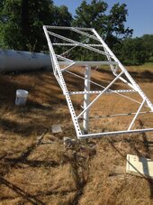
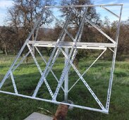
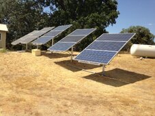
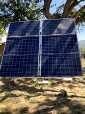
Here's a pic of some of my adjustable ground mounts. I have built several array frame that can handle between three and six large residential panels. I'd recommend copying that rather than something rollable. These arrays that are adjustable for both azimuth and declination have survived storms that have toppled the Oak trees you can see in the background.
 

Attachments

  • 024.JPG
    024.JPG
    284.7 KB · Views: 5
  • array frame snip.jpg
    array frame snip.jpg
    185.5 KB · Views: 5
  • 032.JPG
    032.JPG
    462.3 KB · Views: 6
  • Array frame 5_point_zero.png
    Array frame 5_point_zero.png
    1.4 MB · Views: 5
BTW, if you haven't really decided yet on your system voltage, I'd suggest taking a step back and do a bit more planning. What exactly do you intend to power? Is this supposed to be a backup power-supply during blackouts? Disconnecting two 12V batteries just to charge them at 24V is not going to work very well. You'd be better off permanently wiring them at your system voltage and leaving them as is.

You're better off coming up with an itemized list of what you want to power, and for how long, then we can properly design something for you that will not let you down. Don't run out and buy anything else until the plan has been fleshed out.

For a home backup system, I would go with at least 24V. But, how big are these batteries, and what is their chemistry? That should be part of the planning process.
 
Thanks again for all of the helpful information @MichaelK. I really like your mounts. I have put quite a bit of thought into the rolling cart idea and know someone who built one and has been using it for a short time with success but he also has a system of driving stakes into the ground and tethering the cart (not sure if it has seen more than 20-30 mph winds yet though). The thought on the cart was that it can be moved around to keep grass growing underneath. As far as use purposes, this system is going to be my first build but I have some experience with pre-built stations (several Bluetti power stations over the past few years) and mainly have used them for just occasional use of electronics (more keeping everything ready in case of power outage). I have been experimenting with different setups as far as portable panels go and have had a lot of fun learning about the different ways to set up multiple panels. This particular project is intended to do two things: 1) To learn more about solar while building my own system with batteries that I have acquired (mainly LiFePO4 100 Ah 12.8V Mini batteries), 2) redundancy to back up prebuilt stations in case of failure, and 3) to get some rigid panels in use to avoid having to constantly set up portable panels when needing to charge. With all of that in mind, I have not yet run PV wire for a permanent set up but needed to get the rigid panels purchased due to other timing circumstances. If I am successful in running a permanent wire into the structure, I may try to set up something like an entertainment center or full size refrigerator on the system full time but that would likely be it. I wavered between going with a 12V or 24V setup and finally decided on 12V simply because of the compatibility with so many things (Powered USB outlets, phone chargers, etc.) and the fact that I could always remove the 12V accessories (and inverter) and use it as a 24V system by rewiring batteries in series. I also looked at idle running power for inverters (specifically Samlex inverters that I have had experience with) and determined that 24V would actually consume more power at idle than 12V (although by only a few watts). I figured that I would build the system for 12V with thicker wires and I could always convert to 24V if I wanted to and the thicker wire would still work fine. I like the Victron stuff and already have a Smart Shunt so that is where I was going to go for the SCC. I was preparing to purchase the wire, fuses, and all of the other stuff today to build the station but I appreciate you taking interest in my setup so I am eager to hear your thoughts on it if you have any additional. I actually posted a diagram and there was discussion in another post (https://diysolarforum.com/threads/diy-solar-plans-is-this-a-safe-setup.75208/page-2#post-958743). Regarding the purchase of rigid solar panels, I probably just got ahead of myself as I wanted to get something relatively small and lightweight so that it could be moved about and stored for storms, lawn mowing, etc. and that is the reason for the cart idea. Please feel free to share your thoughts as I am eager to hear more from you and anyone else that might have ideas. Thanks.
 
Thanks again for all of the helpful information @MichaelK. I really like your mounts. I have put quite a bit of thought into the rolling cart idea and know someone who built one and has been using it for a short time with success but he also has a system of driving stakes into the ground and tethering the cart (not sure if it has seen more than 20-30 mph winds yet though). The thought on the cart was that it can be moved around to keep grass growing underneath. As far as use purposes, this system is going to be my first build but I have some experience with pre-built stations (several Bluetti power stations over the past few years) and mainly have used them for just occasional use of electronics (more keeping everything ready in case of power outage). I have been experimenting with different setups as far as portable panels go and have had a lot of fun learning about the different ways to set up multiple panels. This particular project is intended to do two things: 1) To learn more about solar while building my own system with batteries that I have acquired (mainly LiFePO4 100 Ah 12.8V Mini batteries), 2) redundancy to back up prebuilt stations in case of failure, and 3) to get some rigid panels in use to avoid having to constantly set up portable panels when needing to charge. With all of that in mind, I have not yet run PV wire for a permanent set up but needed to get the rigid panels purchased due to other timing circumstances. If I am successful in running a permanent wire into the structure, I may try to set up something like an entertainment center or full size refrigerator on the system full time but that would likely be it. I wavered between going with a 12V or 24V setup and finally decided on 12V simply because of the compatibility with so many things (Powered USB outlets, phone chargers, etc.) and the fact that I could always remove the 12V accessories (and inverter) and use it as a 24V system by rewiring batteries in series. I also looked at idle running power for inverters (specifically Samlex inverters that I have had experience with) and determined that 24V would actually consume more power at idle than 12V (although by only a few watts). I figured that I would build the system for 12V with thicker wires and I could always convert to 24V if I wanted to and the thicker wire would still work fine. I like the Victron stuff and already have a Smart Shunt so that is where I was going to go for the SCC. I was preparing to purchase the wire, fuses, and all of the other stuff today to build the station but I appreciate you taking interest in my setup so I am eager to hear your thoughts on it if you have any additional. I actually posted a diagram and there was discussion in another post (https://diysolarforum.com/threads/diy-solar-plans-is-this-a-safe-setup.75208/page-2#post-958743). Regarding the purchase of rigid solar panels, I probably just got ahead of myself as I wanted to get something relatively small and lightweight so that it could be moved about and stored for storms, lawn mowing, etc. and that is the reason for the cart idea. Please feel free to share your thoughts as I am eager to hear more from you and anyone else that might have ideas. Thanks.
I might also add that the reason for the larger amperage on the SCC was that I would like to be able to get a bunch of portable solar panels out in case of emergency and be able to get as much power as possible when needed (possibly future expansion of rigid solar panel setup).
 
I did some additional math and want to ensure I am correct in my understanding. Looking just at the 300 watt panel and the 100 watt HQST panel, they have Vmp values of 17.5V and 17.6V respectively, so if you put them in parallel, wouldn't that mean that you could potentially still get 399.35 watts (ideal conditions) because the max power current (Imp) values of 17.14A and 5.68A would add together (22.82A) multiplied by the limiting voltage (17.5V). If so, I would think you would need to put an inline MC4 15A fuse on the positive side of the 100 watt panel to provide short circuit protection from the larger 300 watt panel. I am just wanting to confirm that my calculations are correct. Thanks,
 
I did some additional math and want to ensure I am correct in my understanding. Looking just at the 300 watt panel and the 100 watt HQST panel, they have Vmp values of 17.5V and 17.6V respectively, so if you put them in parallel, wouldn't that mean that you could potentially still get 399.35 watts (ideal conditions) because the max power current (Imp) values of 17.14A and 5.68A would add together (22.82A) multiplied by the limiting voltage (17.5V). If so, I would think you would need to put an inline MC4 15A fuse on the positive side of the 100 watt panel to provide short circuit protection from the larger 300 watt panel. I am just wanting to confirm that my calculations are correct. Thanks,

That sounds right.

I am not sure about the fuse exemption for panels with unmatched fuse rating but it wouldn’t hurt apart from minor extra cost and point of failure. You will want the fuse to exceed 1.56* ISC of the small panel and less than the max fuse rating.
 
All in parallel looks fine. With 30A Imp, 10 awg doesn't meet code (ought to have wire with allowed current 1.56x Isc) but it will work fine.
Supposedly each panel should be fused according to data sheet (20A, 15A, 10A). If you just fused the one with smallest rating that would probably be sufficient. Or don't fuse at all, if not on a dwelling.

You can orient each differently, spread out production during the day.

What charge controller? 17Vmp probably OK for MPPT, but some want more headroom.
 
You shouldn’t need fuses for 2P but I might have missed that it is more in parallel

I think #10 is actually allowed to go to 35A in this application, the 30A limit is on OCPD size. 35/1.56 might be close enough with the rounding rule (I’m not sure what the NEC’s rounding rule is). If there’s 3P I think switching to #8 is a good idea, or at least putting a breaker on #10 in an easy location to reset, to split the difference on risk.
 
3 panels, but only one has "max fuse size" significantly smaller than sum of current from other two panels, so only it would have much chance to blow its fuse.

10 awg has ampacity 40A for 3 current-carrying conductors in a bundle. But NEC only allows 30A. Not sure about exceptions.
This would have 2 current carrying conductors, and maybe in free air for higher ampacity. So if not trying to comply with NEC I wouldn't worry.
If multiple orientations, peak is lower.

Of course that ampacity is based on 90C. Goes to terminals likely rated 75C. Are single wires exposed to they can lose heat to the air?

I find I can get away with breaking rules so long as I don't break too many simultaneously. I fused plastic and shorted wires running excess current through a coil of UF, should have uncoiled it.
 
The limit is due to 240.4(D)(8) which is rather lax compared to the other clauses.


So I interpret this as, since there is no required OCPD protecting the #10, it is allowed to go to 75C column. I guess if the MPPT internally has OCPD that is an interesting edge case. But don’t believe that OCPD is eligible to protect the wire anyway since it’s at the wrong end of the power source.

Problem with the free air allowance is that there is an extra heating derate for being strapped next to a roof (not sure if that is the case in the situation here).
 
That sounds right.

I am not sure about the fuse exemption for panels with unmatched fuse rating but it wouldn’t hurt apart from minor extra cost and point of failure. You will want the fuse to exceed 1.56* ISC of the small panel and less than the max fuse rating.
Thanks. I have a question regarding the fuse size. I have heard that you should fuse panels at or close to the max fuse rating (as more current would destroy the panel) - Is it better to fuse 1.56 ISC? In this example, those two values are somewhat different (1.56 X 6.03A = 9.41A vs Max Series Fuse rating of 15A). I guess a 10A fuse would work as a split of the difference. Just wondering as I have learned a lot from just looking at these threads alone.
 
Thanks. I have a question regarding the fuse size. I have heard that you should fuse panels at or close to the max fuse rating (as more current would destroy the panel) - Is it better to fuse 1.56 ISC? In this example, those two values are somewhat different (1.56 X 6.03A = 9.41A vs Max Series Fuse rating of 15A). I guess a 10A fuse would work as a split of the difference. Just wondering as I have learned a lot from just looking at these threads alone.

I think max fuse rating is usually rounded up to standard breaker size from 1.56 ISC or to make the panel easier to integrate in a parallel string.

I would just match the max fuse rating unless splitting the difference lets me shrink the wires on that side in a meaningful way. 10A vs 15A would likely both be #14 anyway
 
Really interested in the wire size discussion here as well as the fusing topic (those are both topics that I had a hard time getting information on until I got the help from this forum). Regarding the wire size, this wire would not be next to a roof - It would be out in the open laying on the ground or possibly running to the inside of a structure (possibly through an attic?) and would be running to an MPPT controller (Victron 150/45 TR). In the example of only using the two panels (300 watt and 100 watt panel), the overall current at max power would be 22.82A so is the concern that 22.82 X 1.56 = 35.60A (which would exceed the 30A current carrying capacity of 10AWG wire)? Or should I be looking at the Isc of the largest panel in the array (18.85A) as that value multiplied by 1.56 would be less than 30A? Just trying to figure it all out. Thanks
 
Back
Top