diy solar

diy solar

Question about mismatched panel setup

KISS and don't use optimizers.
From my perspective the discussion around optimizers was to get around the very strange current and voltage on that panel wrt future proofing. 17V*17A to make 300W. My hunch is it’s weird like this to work with PWM on 12V systems.

Actually a lot of optimizers might not even be able to handle that current on the input.
 
Last edited:
Threre's gotta be a programmer on here that can make some sort of program where you can put in the VoC, Vmp and Isc, the number of panels, next column again, and do the math. In theory it should be simple?
Midnight solar has already created their string-sizing tool. You can find it here....
 
@MichaelK. I was showing photos of your setup to someone else and they also liked it. They were asking questions about the specifics that I could not answer. What materials were used and do you by chance have any specific plans you are able to share (or just thoughts on the construction). Nice job.
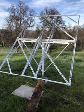
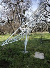
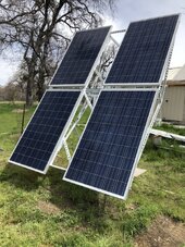
They are all single-pole ground mounts. I really don't have any plans. I basically make each array frame custom depending on what panels I happened to get a good deal on.

I sink a 8 foot section of 3.5" schedule-40 steel pipe 3 feet in concrete, with ~5 feet sticking up above ground. I then slip a four-foot section of capped 4.0" schedule-40 pipe on top of it. A 80" section of doubled unistrut is welded on top of the cap, making a T-post. Two half-channel unistruts ~60" long are welded at ~45 degrees to form trusses on the T-post.

The actual panel frame is also welded out of full-channel unistruts, with the spacing of the unistruts matching the mounting holes on whatever panels I bought on sale. The panel frame is bolted on the T-post with four heavy security-door hinges. I make diagonal braces out of unistruts, and most recently rebar to keep the panel frame rigid. I also weld bent unistrut pieces on the back side of the panel frame to keep it rigid in the Z-dimension.

Here are are some pics from different angles to let you see how I built the array frames. These array frames can be adjusted for both azimuth and seasonal declination. They had held up to years of winter storm damage now. Look at the Oaks in the background. Storms that have knocked over some of those Oaks did not damage any of my arrays. They've also held up to a snow load of 4 feet.
 

Attachments

  • IMG_0778.JPG
    IMG_0778.JPG
    304.9 KB · Views: 5
  • IMG_0776.JPG
    IMG_0776.JPG
    366.2 KB · Views: 5
  • IMG_0780.JPG
    IMG_0780.JPG
    347.3 KB · Views: 5
Midnight solar has already created their string-sizing tool. You can find it here....

That's not what I'm talking aboit. I'm thinking something that would let you put in different panels/strings together and would calculate how much one panel is nerfing the other panels.

That would be a really good way to see how much your system is getting ruined by adding that 100w panel to your string of 450w panels in parallel with this old 50w flexible you inherited and so on.
How is ChatGPT etc's math hallucination for solar?
 
They are all single-pole ground mounts. I really don't have any plans. I basically make each array frame custom depending on what panels I happened to get a good deal on.

I sink a 8 foot section of 3.5" schedule-40 steel pipe 3 feet in concrete, with ~5 feet sticking up above ground. I then slip a four-foot section of capped 4.0" schedule-40 pipe on top of it. A 80" section of doubled unistrut is welded on top of the cap, making a T-post. Two half-channel unistruts ~60" long are welded at ~45 degrees to form trusses on the T-post.

The actual panel frame is also welded out of full-channel unistruts, with the spacing of the unistruts matching the mounting holes on whatever panels I bought on sale. The panel frame is bolted on the T-post with four heavy security-door hinges. I make diagonal braces out of unistruts, and most recently rebar to keep the panel frame rigid. I also weld bent unistrut pieces on the back side of the panel frame to keep it rigid in the Z-dimension.

Here are are some pics from different angles to let you see how I built the array frames. These array frames can be adjusted for both azimuth and seasonal declination. They had held up to years of winter storm damage now. Look at the Oaks in the background. Storms that have knocked over some of those Oaks did not damage any of my arrays. They've also held up to a snow load of 4 feet.
Thanks. This is a pretty neat system and looks like a sturdy way to go.
 
Panels in series is how we get away with small gauge wire and reduce IR loss.

#1 rule is do not exceed max allowed PV voltage into SCC or inverter.
Multiple panel Voc by number in series, and multiply by 1.16 for conservative adjustment for cold weather. Or get temperature coefficient from data sheet, historical record cold for your location, and calculate the actual increase in voltage.

Same wattage at twice the voltage, half the current, will be 1/4 the loss.

It is great if you can get loss under 1% or under 3%, but that isn't required. A loss of 10% or more at peak output is OK if you decide it saves you money on wire.

Series, all panels have to be same or vary close to same orientation.
Parallel strings can have different orientation.

KISS and don't use optimizers.

If panels are on roof and > 80 Voc, you're probably required to have RSD. Optimizers and module-level monitoring are available at some price above RSD.
This is all pretty fascinating. I had the voltage hard limits in mind when I started but have been learning much more from this forum. Regarding orientation, I had never heard anything about guidelines for series as I assumed that as long as you had the same (or very similar) panels, arrays could be oriented horizontally or vertically and would not need to match. More good information.
 
Two different meanings of "orientation".

Portrait, Landscape, or anywhere in between doesn't matter at all, except or mechanical issues and more importantly how shadows encroach. Because panels typically have 3 diode-bypassed sections, you may be able to have shadows cut off only 1/3 rather than 100% of a panel's output.

The orientation I was referring to was SE vs. SW, to catch morning vs. afternoon sun. All the inverter manufacturers used to say multiple strings connected in parallel all had to have the same orientation and tilt, face exactly the same way. That isn't true. All oriented same on a given MPPT was found to yield about 2% more power than combining differently oriented strings on a single MPPT. But now that you can buy PV panels for about the same price as a SCC or inverter, it can be better to put morning and afternoon strings in parallel into one MPPT, can over-panel to about 140% without clipping. Get 40% more from SCC or inverter while wasting only about 2% of PV panel capability.

For an off-grid system, multiple orientations is more important than for grid-tie net metering, because it keeps battery full later in the evening, leaving more power for night. (whether on multiple MPPT or single.)
 
From my perspective the discussion around optimizers was to get around the very strange current and voltage on that panel wrt future proofing. 17V*17A to make 300W. My hunch is it’s weird like this to work with PWM on 12V systems.

Actually a lot of optimizers might not even be able to handle that current on the input.

17A is more current than (normal size) PV cells produce. Probably two strings in parallel.
Hack and rewire in series.

Or use for other purposes (e.g. a PWM controller) and buy more panels that work together.
Or find cheap panels from typical grid-tie systems and forget this mismatched batch.
 
Thanks for the advice. I didn’t even think about the metal conduit encasing as that is a good idea (I have a lot to learn). Thinking about the setup we were currently discussing, what if I had another identical 300 watt panel in series (and no other panels) so that the amperage was not increased - Is my thinking correct that you could potentially still get the full 600 watts from the two panels and still be safe using 10AWG wire into a structure? Or do you have to account for the possibility that more current might occur if a short developed in one of the two panels?
Following up on this thought, is metal conduit an NEC requirement for all PV wire inside a building? For example, what if your panel (or array) had a peak current of 15A and you were running 10AWG PV wire (well within the rated carrying capacity of the wire), would it be required to run through conduit? Obviously it is still a good idea but would it be a requirement? Just wondering as I have not dug into the NEC requirements yet.
 
Following up on this thought, is metal conduit an NEC requirement for all PV wire inside a building? For example, what if your panel (or array) had a peak current of 15A and you were running 10AWG PV wire (well within the rated carrying capacity of the wire), would it be required to run through conduit? Obviously it is still a good idea but would it be a requirement? Just wondering as I have not dug into the NEC requirements yet.

By default yes metallic conduit is needed for PV DC circuits inside. There may be some edge cases based on voltage.
 
By default yes metallic conduit is needed for PV DC circuits inside. There may be some edge cases based on voltage.
Thanks for all of the help everyone. I now have more questions related to this setup and wanted to get some input.

1) On the topic of mismatched panels, if I have a panel that is rated at 38V, 11A at max power and I have 2 other panels that are identical and are rated at 20V, 5A at max power (each), couldn’t I wire the the two 5A panels in parallel to effectively create a panel with 20V and 10A and then wire that setup to the 11A panel in series to get a setup that would yield around 58V, 10A at max power?

2) In the setup above, would I need to fuse anywhere (if the parallel panels do not need to be fused when just combining them together- Max fuse rating is more than two of them together)?

3) Unrelated to the questions above but on the same setup, I have noticed a lot of discussion on whether or not you should connect a Class T fuse directly to a battery (or busbar) without use of a fuse holder. I thought that connecting the fuse directly to the power source was the way to go because it seems like otherwise there would be a run of wire between the power source and the fuse holder that could be damaged or catch fire (which defeats the idea of the fuse). This may sound like a rookie question but am I incorrect in thinking that direct to the power source would logically be the way to go to avoid the most damage?

4) Somewhat related to 3) above, if I am connecting two Lithium Iron Phosphate batteries in parallel (or series for that matter), is a Class T fuse needed for the connection between the two batteries?

I apologize for the long post but the questions keep coming and this forum post has been most informative so I was hoping to get some feedback before proceeding. Thanks.
 
Yes, either 11A in series with 5 + 5 = 10A, or 38V in parallel with 20 + 20 = 40V.

However, in the first case, if 5A panels were shaded and 11A pushed through bypass diodes of one, would burn the diodes. (Parallel diodes aren't expected to share current evenly, one that takes more gets hotter and takes even more.

In the second case, shorted 5A panels get backfed 11A, maybe a fuse helps. Although, it's recommended fuse size may not blow at 11A or whatever lower amount the sun is producing.

I think either will work, just has some potential issues.


Fuse holders are a convenient way to hold and replace fuses, without wires flopping around that might short.
Fuse directly on battery terminal might provide more leverage than desired. If class T fits there, could work.
(If using MRBF, a fuse holder is required to avoid bridging past the fuse.)

Fusing individual batteries may be better, but I don't think a failed battery would sink so much current as to blow the fuse. Maybe a disconnect per battery and fuse before long cable to load? Different approaches depending on anticipated failure mode. Best is probably disconnect and fuse per battery. Mostly BMS takes care of things, but concern is if it fails.
Thanks for all of the great input. Should I decide to go with fuse holders for the two Blue Sea Systems 5116 Class T fuses I have, does anyone know where I can get them? I seem to be having a hard time finding anywhere that sells the holders. I found a Blue Sea Systems model 5007100 (which I think has the correct compatibility) on eBay but it is listing the max amperage as 160a when I thought it was supposed to be for a 200 amp fuse. Just trying to find a place where I could purchase the holders. Thanks again.
 
As I understand it there are 2 sizes of class-t fuse holders depending on if you need more or less than 200a. The 200a+ size mounts are much more common which makes finding the 160a ones difficult to find. The easiest way is to find the fuse size you need and find a version that comes with the mount.

A warning though, the wonderful thing about standards is that there are so many to choose from so once you've picked a brand and size, you're limited to that brand and size mostly.
 
Back
Top