diy solar

diy solar

Question to do or not to do

Hagshur

New Member
Joined
Apr 20, 2020
Messages
6
Hi all freinds
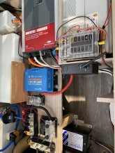
I have in my caravan system with the following main components:
1. 4 hqst 100 watt connected with junction box
2. Victron solar charger 100/30
3. TBS 2000 inverter
4. Main negative busbar
5. Main positive bus bar
6. And NS shunt and 250 amp fuse
7. TBS advance monitoring
My question is:
All cacles today going to the busbars except the solar panel charger + and -

should I move them the the busbar also ?
so I can see the solar input in TBS monitor and not on the victron mppt app?
 
I don't know what "TBS advance monitoring" is.

Assuming it's a typical battery monitor with a shunt, the typical configuration is:

Battery (-) --------- Shunt ----------- Busbar---------- (-) Loads and charging

Battery monitors configured as such see the NET flow to/from the battery.
 
Yes, what soobler said. Battery negative terminal to nothing else but the battery side of the shunt. Everything, everything else to the load side of the shunt. Drains and chargers. Oh? What is a cacles? Similar to a cable?
 
Here’s my system
Diagram recommended from this channel
 

Attachments

  • 11501B5F-C5C8-4441-B21B-A2BCC1DD0A2E.jpeg
    11501B5F-C5C8-4441-B21B-A2BCC1DD0A2E.jpeg
    160 KB · Views: 25
Nope. I can't even see the battery. And my world is turned upside down by the inverted Victron.

And I still don't know what a TBS is.
 
Last edited:
Ok anyway the question is pretty simple
Let’s focus only the victron charger
Today
From battery+ and - goes to shunts + and - goes thats connected to battery also.
But from solar panels junction box + and - goes to the victron
So
What’s the right way to get solar data on my TBS display ( it’s the same as victron one)
 
Again,

Battery (-) --------- Shunt ----------- Busbar---------- (-) Loads and charging

Would help if I knew what a TBS is.
 
Ignore the word TBS let’s say it was victron
Like this one exactly just the manufacturer is TBS electrics great company btw?
 
Okay, so, it's like this again:

Battery (-) --------- Shunt ----------- Busbar---------- (-) Loads and charging

The shunt should be attached to the (-) of the battery or to a wire coming from the battery (-). The bus bar should be attached to the other end of the shunt, and the (-) of the loads and charge controller should be attached to the (-) busbar
 
Last edited:
@Hagshur, are you asking after you hook the shunt as snoobler said, where do you put the little red cable that comes out of the shunt, then on my BMV-712, I put that to the positive terminal on the battery. I've got a couple of things left to hook up, and that red cable is one of them. I can even attach a second little red cable to the mid-point batteries to monitor those.

For whatever thing you are asking about, I don't know, but I found where to hook my cables up on the paper instructions. For whatever reason, Victron does not publish those online.
 
I don't know what "TBS advance monitoring" is.

Assuming it's a typical battery monitor with a shunt, the typical configuration is:

Battery (-) --------- Shunt ----------- Busbar---------- (-) Loads and charging

Battery monitors configured as such see the NET flow to/from the battery.
Is item 7 from his list the unknown?
 
Yes they do. There's a quick install guide for each model. Here's the 712:

https://www.victronenergy.com/upload/documents/BMV-712-quick-installation-guide.pdf
When viewing the product, click the download button and select "quick install guide" from the options at left.
These are the diagrams I got in my printed sheet that did not match the online version. Basically shows a 2S3P battery bank.

The first pages were the same, but these two pages were added. For some reason I got a BMV 702/710 quick installation guide with my 712, but up to the two pages I included it is the same.
 

Attachments

  • Multiple Parallel Batteries.pdf
    1.1 MB · Views: 7
  • Multiple Parallel Batteries-2.pdf
    1 MB · Views: 4
Back
Top