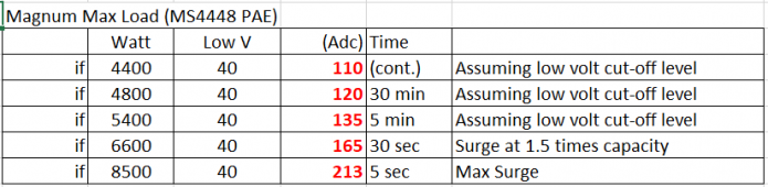
Surge specifications aren't normally used.
8500watt is a few seconds, most breakers have some room for surges.
I don't know about DC, AC have 4 types A-D where D can handle 20x rated amperage for a short time.
As far as I can tell, all my DC breakers are C class, 5 to 10 time.
For BMS, anything above 100A I can not advice Mosfet based.
While fets use little power them selves, they do give a voltage drop.
0.5 volt at 20A isn't bad.
At 100A, it's an 50 watt heater...
I really do prefer contractor based.
It's not new invention, DC with higher capacity.
Most known things use Contactors.
Starting your car (starter contractor) or golf cart (continuous use contractor)
And yes, both use electricity when working. My 400A about 7 watt.
Normally speaking you have 2 contactor, one to stop charge and one to stop discharge.
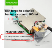
DIY solution like using the relay not to make the Contactor click, but the power switch of the inverter are used a lot also.
BMS like Chargery and electrodacus use relay to turn on the contactor.
Or your inverter
")
Same for your charger, if it have a power switch, you could use the relay to turn it off when one cell reach 3.65v.
In solar situation, most solar controllers (stand alone or build in for hybrid) always work when there is enough light.
They have their charge profile, and are unaware of imbalance for the cells.
Most don't have a power switch!
In more complex installations, I would suggest DIYBMS.
You have 4 controllable relays.
That can be
AC Contactor,
DC for charge,
DC for discharge,
Fan for cooling,
Turn on coffee machine
Anything you like.
In my setup I stop AC power at 2.8v
But continue DC usage
I have several things running of DC.
One of them my security system.
It's all low capacity, so should last days on the 2.8v. (+50 kWh LiFePO4 powerwall)
It it does go too low, there is a Contactor for that as well.
For your straightforward setup:
Power backup with 48v (S16) 14 kWh LiFePO4, you won't use 100A
Realistic, when the grid goes down, you won't be using your high capacity equipment.
Clothes dryer are known energy hungry, bit not directly essential during the few hours blackout.
How much will you realistic use?
2000 watt?
Your setup build for 6 hours backup?
Don't overthink it.
A dumb Daly, set and forget type will work perfectly.
(Split port)
Sure, you don't see what's going on.
You don't need to.
First time your multimeter will give you all the information you need.
Charge each individual cell to 3.65.
Once finished, place all 16 in parallel and charge again to 3.65.
Then you are sure all are fully charged and balanced.
Make your installation, connect charger and inverter.
Done.
While LiFePO4 doesn't self discharge as fast as lead acid, it still does.
Tickle charge like lead acid?
Your cells won't be happy.
Ideally you top up once a month.
And obviously after a blackout.
Don't let your charger on 24/7.
Your battery will last year's longer with just once a month top up.
As it's a emergency setup.
You aren't going to check the cell voltage every day of few hours.
You simply should not care.
I doubt you care about the rechargeable toothbrush or shaver...
As always, during installation:
Work clean.
OCD like clean you busbars and terminals.
Aluminium oxidise in 20 seconds to a level it will effect the conductivity.
Use antioxidation compound like ox-gard
Your busbars should not be clean pure copper, but plated. Aluminium and copper aren't friends (galvanic corrosion)
Don't (!!!!!) Use the screw you get with the cells!!!.
Use 304 stainless steel studs / rod/ headless bolts.
The weak aluminium thread needs to be fully used.
Twisting motion force with a screw/bolt is really stressful on the weak thread.
Get digital Torquemeter. They are about $30,-

It's Impossible to feel equal force by hand, and the clamping force will effect the overall Balance.
Minimal 3.5 Nm, advice 4Nm
You will strip a healthy thread with +5.xNm
Above 7Nm you have the risk to twist the terminal in its plastic holding.
I tried on defective cell and it started spinning at 9Nm
(Re-tapped the thread with M8, and used epoxy for additional strength.
Obviously, that is stronger then 9Nm!
)
If you want to avoid issues with pulled out threads, clean the thread, clean the stud (acetone) and use JB weld epoxy or similar.
When you first scrub the terminal clean, apply ox-gard, and clean the thread, the epoxy that you spill won't stick to the aluminium.
Some Epoxy with a toothpick on the side tread of the terminal, incert the stud and wiggle it a bit while twisting it down.
Excess epoxy will go via the thread up, and easy be removed with a toothpick.
After this, your (pre-charged to 3.65v) cell is ready for final installation
Good luck!


 a.aliexpress.com
.jpeg")

 ), but also like idea of being able to trouble shoot if need be.