diy solar

diy solar

Renogy Battery Monitor

markjel

New Member
Joined
Sep 4, 2023
Messages
12
Location
milton keynes
Afternoon all, am looking for some help with a renogy system.

I have installed 2 x Renogy 175 Watt Solar Panels, 40amp Renogy Solar Charge Controller, 2 x 135ah Sealed Leisure Batteries in paralell, 1 x Renogy 3000 watt inverter, and the renogy battery monitor with the shunt.

Everything is connected and working fine apart from the act that the battery monitor is showing a constant power draw of between 20 and 30 watts, even with everything switched off. I have disconnected everything one lead at a time and the power draw is constantly there unless I disconnect the solar feed. With the feed disconnected, the power draw (bottom right) goes to zero, as soon as its reconnected, it jumps to between 20 and 30 watts and stays there.

I do not understand how or why this is happening, can anyone help guide me towards a solution please?

Thanks,


Mark
 
Shunt installed backwards ??? When you power up something with the inverter does the monitor show + or- ?
 
Thanks for the reply, when the inverter powers up it shows as + power, tried reversing shunt, and still get the same constant power draw showing on the monitor, but only when solar panels are connected.
 
A running inverter should show as -. Maybe the 20-30 watts is your solar panels just charging your batteries through a reversed shunt
 
Last edited:
A diagram showing your circuit connections would help the discussion.
 
The + leads look OK . Your - leads need a redo. ALL the - wires go through the shunt.
Neg lead from right battery (shunt B-) needs to go to left battery. To balance the flow, the + on one battery goes to the + bus bar and the - lead on the other battery goes to the bus bar.
Neg lead from - bus bar needs to go to P- on shunt.
If you have enough wire connect the inverter to the bus bars so all the loads are balanced.
 
If you disconnected the "-" at the SCC and Inverter, then you might need to calibrate the Shunt. When you connect the SCC it might be the MPPT's drawing power to look for power from the Panels and/or Rapid Shutdown. Look up "black start" to see all the things needed to be powered just to start producing power.
 
Last edited:
Thank you, so much for your help.

I think I understand all of that apart from "Neg lead from right battery (shunt B) needs to go to the left battery". Do you mean that I connect Shunt B- to Neg of left battery, and then just link Neg on left battery to Neg on right battery?

If I draw a new picture of my understanding of your advice tomorrow would you be so kind as to check it for me please?

Last question - would the way I have wired this be causing the constant power draw readings I am getting on the monitor? Is causing me a great deal of frustration!
 
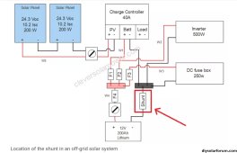
Hi Mark, you need to reconsider the complete circuit and add over current protection fuses. A typical circuit,Screenshot_20230905-200359_Chrome~2.jpg

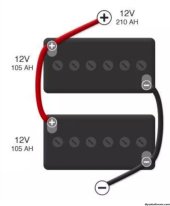
The two batteries in parallel make up one 'big' battery, wire as show.
Screenshot_20230905-201059_Chrome~2.jpg

The 20 to 30 watt current flow is probably the standby current of the inverter, switch off when not in use.

Note the correct use of high current rated buss bars in the diagram , this reduces the cables connected to the battery terminals to a minuim, for more reliable connections. Cable size and fuses must be suitable for the expected currents.

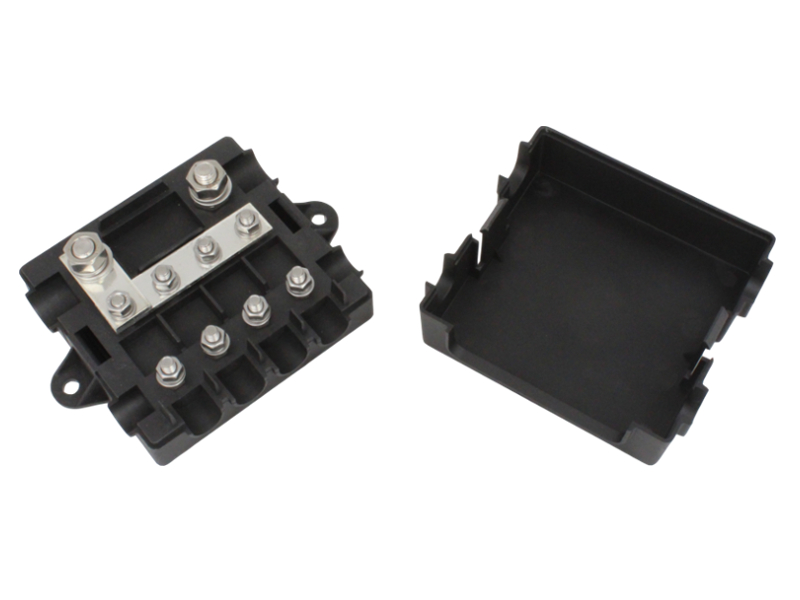
Since you are in the UK a useful source of cables, fuses and other stuff, is 12 VoltPlanet. For example your positive buss bar and fuses can be combined in one unit,

The 3000 watt inverter is too much for your two batteries unless you limit the AC load. Do you realy need this much power?
What AC loads do you intend to power?

Mike
,
 
Last edited:
^ That is a good layout.
Batteries parallel
Battery #1 + to Battery #2 +
Battery #1 - to Battery #2 -
Bus bar + to battery #1
Bus bar - to battery #2
Clear as mud right??
 
Hi Mark, you need to reconsider the complete circuit and add over current protection fuses. A typical circuit,View attachment 166093

The two batteries in parallel make up one 'big' battery, wire as show.
View attachment 166095

The 20 to 30 watt current flow is probably the standby current of the inverter, switch off when not in use.

Note the correct use of high current rated buss bars in the diagram , this reduces the cables connected to the battery terminals to a minuim, for more reliable connections. Cable size and fuses must be suitable for the expected currents.

Since you are in the UK a useful source of cables, fuses and other stuff, is 12 VoltPlanet. For example your positive buss bar and fuses can be combined in one unit,

The 3000 watt inverter is too much for your two batteries unless you limit the AC load. Do you realy need this much power?
What AC loads do you intend to power?

Mike
,
Thanks Mike,

I have switched the inverter off and am still showing 20-30 watts power draw, which I expected to be much closer to zero?

I have a microwave, kettle, air conditioner unit and truma eater heater, I will only use a max of 2 of these at any one time but went for the larger inverter as thought it was better to have more power capacity than I would ever need. Should I have gone for a 2000 watt inverter instead? Could the size of the inverter be causing the permanent power draw?
 
Inverter damaged??? Un bolt the - lead and see what happens to the 20-30 watts
 
First off you need to rewire the shunt as indicated in my diagram. Renogy stuff can be faulty on delivery, a lot of returns are sent back out, so that's a possibility. Disconnecting each positive connection to the battery in turn may show what part of the system is using 30 watts. That's over 2 amps, does the Renogy shunt display that current value?


have a microwave, kettle, air conditioner unit and truma eater heater, I will only use a max of 2 of these at any one time but went for the larger inverter as thought it was better to have more power capacity than I would ever need
Those are high power items. It's not so much the inverter that's the issue but the batteries. The sealed leisure batteries you have, like most 'leisure' batteries sold In the UK, are not true deep cycle batteries and will have a short life. Also practicality cannot run high power appliances for long. You have 130Ah x¥,2 at 12v , 3120 water hours. To get any useful life from the lead acid batteries its recomended not to use more than half the capacity, thus you have, say, 1600 watt hours of useful energy.
Life gets worse with lead acid batteries when you discharge at high currents as the effective energy becomes lower.

You solar, two 175 watt panels, on I guess, a camper van roof , will deliver, on a good day in summer around 1200 watts per day.

Sorry to sound so negative but your batteries are not realy suitable for the high current the inverter will need to power those AC appliances. Even if they power a microwave for half an hour, the input from the solar will not be able ro recharge the batteries enough.

If you intend to use your camper away from 230V AC shore power and still use the appliances, you need to consider a redesign. More and better batteries, idealy lithium, more solar, additional charging from the alternator, B2B charger.

Or with the system as shown, accept you are duration and power limited for those appliances. Do the sums regarding power , watts.

What you have is a useful setup for 12v appliances , say led lights, water pump, 12v fridge, phone changers .

Are you using any guide to help with your electrical system, book, you tube, forum ( other than this)?
 
Thanks for the detailed reply. I disconnected each circuit in turn yesterday and the only way I can get the renogy monitor to show close to zero watts is when the SCC input to the battery is disconnected.

I forgot to include that there is a ctek charger feeding into the batteries as well from the alternator, plus a 12 volt charger that kicks in on shore power too. I only really expect to use 1200-1500 watts of ac power when off grid.
 
way I can get the renogy monitor to show close to zero watts is when the SCC input to the battery is disconnected.
This suggests the Renogy controller is faulty or less likely the Renogy monitor is faulty. With the controller disconnected from the system, connect other known DC loads and evaluate that the monitor readings are as expected.
Good luck with Renogy on getting replacement.
 
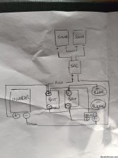
Thanks for your help everyone, this is where I'm at:

Have reconfigured wiring as per above, so all the +ve connections are on the + of battery 1, and all the negative connections are on the shunt on the -ve of battery 2.

I am getting a watts reading of between 4.5 and 5 watts constantly, unless I disconnect the solar, the watts reading then drops to between 1.5 and 2.

Is the conclusion that there actually is something drawing power that I cannot trace, or that either the SCC or Battery Monitor is faulty, or is there anything else I can try?

Thanks,

Mark
 
Well 5 w is better than 30w. So your headed in the right direction. A basic question, after the rewire is the 5w showing as + or - ?
 
Back
Top