Decto
New Member
Hi all,
Joined today so I could view some of the images, so really didn't expect to be posting a question this soon.
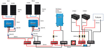
I have setup a solar shed as a project to get some experience over the next 12 months or so before commiting to a full house solar + battery install.
Bought this setup about 6 months ago, however only up and running 2 days ago due to deciding to fully insulate the already very full shed before starting, some illness and a pretty cold and wet UK winter.
Fired up 2 days ago, everything seems to be working fine, both MTTP charge well, hitting 40+ amps depending on time of day, Max approx 60A combined.
Multiplus seems OK, using battery / solar as priority until <30% SOC (I think, this needs some optimisation).
Have run the thermal camera around a few times, no hot joints etc.
Initial settings.
LiFePO4
Absorb 14.2V, 1 hr
Float 13.5V
The issue.
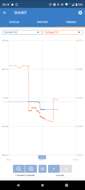
It's dark so no PV input, Multiplus inverting, not charging.
Randomly tonight I remembered I have a clamp meter, I had be wondering about how to monitor parallel DC batteries to check end of charging etc.
With my load of ~8A running I found one battery was proving all the current, the other was zero.
I checked the terminal voltage and both batteries showed 13.32V, smart shunt and inverter agreed.
Measured on the crimp lug and on the battery terminal.
I disconnected the negative of the zero amp battery then remeasured.
The zero amp battery now showed 13.10V (the same as both when delivered), the other battery remained at ~13.3V
I applied a 3A LiFePO4 charger from other small batteries to the zero amp battery and immediately battery voltage hit 14.4V and it said full.
On disconnect and 5 minute hold it was back to 13.10V.
I powered down, then swapped so the system was connected only to the zero amp battery.
On applying the 8A load, the voltage of this battery increased to ~ 13.50V before dropping slowly to 13.31V over the next 10 minutes where it held.
I then disconnected the load and let both batteries rest for 30mins.
Voltage of each was 13.30V + 13.31V (zero amp) so I reconnected in parallel.
On a restart and reapplying the 8A load there was a 50/50 current split between batteries as I'd expect.
My meter actually reads 13A DC at the multiplus and 6.6A DC from each battery though the multiplus and smart shunt say ~ 8A.
Load is a little under 100W so 8A seems closer, main point is that it is now splitting the load equally between batteries.
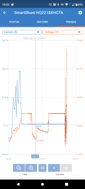
I did have a battery voltage spike today which showed ~ 15.5V for a single reading on the smart shunt.
This happened after applying a 20% overload (heater) to the multiplus for a couple of minutes to check connections with my thermal camera.
The multiplus dropped into charge mode, when I was actually expecting it to switch to AC throughput.
On disconnecting the load, there was a battery voltage spike for a couple of seconds.
Possibly this may have disconected the BMS on one battery, however I don't understand why this would still have a terminal voltage of 13.1V without supplying current. Unsure how to avoid this in the future if using high loads.
Realistically, the max loads will be ~ 200W, typically 100W or less. The multiplus was sized to allow startup of inductive loads such as non inverter fridges and freezers.
From what I'd read the 800VA would alarm with overload in some instances, while the 1200VA did not.
So, it's odd. I ended up with what seems like a battery in idle, not a BMS behaviour I've seen in the small stuff I've played with before.
Unfortunatly these have dumb BMS so there is no data on what is happening.
Some more testing to do, but curious if anyone else has similar experience.
I think I'll also be building an arduino project to monitor current per battery with some CT clamps.
Image below
Joined today so I could view some of the images, so really didn't expect to be posting a question this soon.
I have setup a solar shed as a project to get some experience over the next 12 months or so before commiting to a full house solar + battery install.
Bought this setup about 6 months ago, however only up and running 2 days ago due to deciding to fully insulate the already very full shed before starting, some illness and a pretty cold and wet UK winter.
Fired up 2 days ago, everything seems to be working fine, both MTTP charge well, hitting 40+ amps depending on time of day, Max approx 60A combined.
Multiplus seems OK, using battery / solar as priority until <30% SOC (I think, this needs some optimisation).
Have run the thermal camera around a few times, no hot joints etc.
Initial settings.
LiFePO4
Absorb 14.2V, 1 hr
Float 13.5V
The issue.
It's dark so no PV input, Multiplus inverting, not charging.
Randomly tonight I remembered I have a clamp meter, I had be wondering about how to monitor parallel DC batteries to check end of charging etc.
With my load of ~8A running I found one battery was proving all the current, the other was zero.
I checked the terminal voltage and both batteries showed 13.32V, smart shunt and inverter agreed.
Measured on the crimp lug and on the battery terminal.
I disconnected the negative of the zero amp battery then remeasured.
The zero amp battery now showed 13.10V (the same as both when delivered), the other battery remained at ~13.3V
I applied a 3A LiFePO4 charger from other small batteries to the zero amp battery and immediately battery voltage hit 14.4V and it said full.
On disconnect and 5 minute hold it was back to 13.10V.
I powered down, then swapped so the system was connected only to the zero amp battery.
On applying the 8A load, the voltage of this battery increased to ~ 13.50V before dropping slowly to 13.31V over the next 10 minutes where it held.
I then disconnected the load and let both batteries rest for 30mins.
Voltage of each was 13.30V + 13.31V (zero amp) so I reconnected in parallel.
On a restart and reapplying the 8A load there was a 50/50 current split between batteries as I'd expect.
My meter actually reads 13A DC at the multiplus and 6.6A DC from each battery though the multiplus and smart shunt say ~ 8A.
Load is a little under 100W so 8A seems closer, main point is that it is now splitting the load equally between batteries.
I did have a battery voltage spike today which showed ~ 15.5V for a single reading on the smart shunt.
This happened after applying a 20% overload (heater) to the multiplus for a couple of minutes to check connections with my thermal camera.
The multiplus dropped into charge mode, when I was actually expecting it to switch to AC throughput.
On disconnecting the load, there was a battery voltage spike for a couple of seconds.
Possibly this may have disconected the BMS on one battery, however I don't understand why this would still have a terminal voltage of 13.1V without supplying current. Unsure how to avoid this in the future if using high loads.
Realistically, the max loads will be ~ 200W, typically 100W or less. The multiplus was sized to allow startup of inductive loads such as non inverter fridges and freezers.
From what I'd read the 800VA would alarm with overload in some instances, while the 1200VA did not.
So, it's odd. I ended up with what seems like a battery in idle, not a BMS behaviour I've seen in the small stuff I've played with before.
Unfortunatly these have dumb BMS so there is no data on what is happening.
Some more testing to do, but curious if anyone else has similar experience.
I think I'll also be building an arduino project to monitor current per battery with some CT clamps.
Image below
")