Thanks for your input but Deye can deliver 5KW to the backup load so this isn't a problemWith the on-grid setup, when the grid goes down, your AC output goes down too, even with export set to 0. Depending on the inverter, the battery may supply AC to the priority load, but not to the whole house. Don't mess with grid injection, better buy a spare Growatt.
You are using an out of date browser. It may not display this or other websites correctly.
You should upgrade or use an alternative browser.
You should upgrade or use an alternative browser.
Replacing Growatt SPF 5000ES with Deye 5kw
- Thread starter RSahan
- Start date
Just out of curiosity, how did you end up setting your deye inverter. Do you use the ct clamp? I thought that on the ac out(backup) the power is limited to 3kW. I am on the same quest as tou were. Replacing an Easun with a Deye 5kw, preferably without a ct clamp or placing the clamp somewhere closer to the inverter, in possible.
Yes I did use the clamp. You can place it inside the inverters wiring area. Deye 5kW got 5kW on backup side.Just out of curiosity, how did you end up setting your deye inverter. Do you use the ct clamp? I thought that on the ac out(backup) the power is limited to 3kW. I am on the same quest as tou were. Replacing an Easun with a Deye 5kw, preferably without a ct clamp or placing the clamp somewhere closer to the inverter, in possible.
You need to place the CT on grid wire, not backup load. If you do not have anything loads connected on grid side, you can then place it inside the inverterThank you! What if there are no loads between the ct clamp and the inverter? What setting did you use?
Yes, I know it has to be on the grid side. However, normally one should connect this at the entry point of the house, behind the main panel such that the inverter can see all the load of the house. With the current inverter, Easun iGrid IV which can export but I've set it do not export, I do have AC-in on the unit and I power loads on the AC-out, of course on a parallel circuit to the one of the house.
If I would drop in the Deye instead of the Easun, it will have AC-in and AC-out. AC-out will be connected to the current parallel circuit while the AC-in would be connected to the Deye with the CT clamp on that wire, however the inverter will not see any loads between the clamp and itself, which is against the purpose. Maybe I am confusing the purpose of the CT clamp with the one of a smart meter and the CT clamp purpose is to sense the grid current to know how to sync itself to the sinusoid.
So, can the Deye work with the CT clamp on the AC-in and as close, or inside the inverter even as you say and produce the full output on the AC out? What setting should that be? "Zero export to CT" I guess.
Luxpower_Gilbert
Luxpert @Luxpower USA Team
If you place the ct on the service area and you want to support the whole house load then select Zero export to Home(CT), if you only want to support the output load of the inverter then select Zero esport to Load.
"If you place the ct on the service area and you want to support the whole house load then select Zero export to Home(CT)" -> how would this work in practice?
My current setup is the following:
Grid-> House Loads -> Easun AC-in-> Easun AC-out -> parallel circuit with breakers and wall sockets.
The Easun is in the garage with the house interposing, physically, the whole house loads are physically connected to the grid via the old circuit plastered into the walls. Currently, with the Easun I am not able to feed the entire house. It looks like the Easun is feeding something else than the house, but the parallel circuit is going back into the house and garage however not everywhere. So, to some areas I've doubled the wall sockets. I am powering some fridges and freezer, tv, washing machine and some led lamps where I could wire in a hidden way the parallel circuit. Obviously I cannot get to every part of the house circuit without some serious wall damaging.
Now to come back to the two options:
Zero export to Load, would be the same as the current setup I guess:
Grid->House Loads -> CT clamp-> Deye AC-in-> Deye AC-out -> parallel circuit with breakers and wall sockets. Is this correct? If so, this would be the drop-in method that I understand.
However I have no clue how this would work, I am intrigued by it and it's advantages:
Zero export to Home(CT)
Grid->House Loads -> CT clamp-> Deye AC-in-> ??? -> whole house
Questions: is this AC out of the Deye even used in this case?
is the AC-in of the Deye used also to feed the loads?
what is preventing the Deye not to inject in the grid if the CT clamp is next to it? there's no guard so to speak ...
Maybe it looks like I am hard-headed, it could be indeed. I am also biased by the way the Easun is currently wired. The Zero export to Home sounds very good to me as I could reuse the existing house circuit without the need of a parallel circuit, yet placing the CT clamp next to the inverter does not compute for me. How is the inverted even able to detect how much the house loads are?
I've looked again in the manual and the CT clamp is always ahead of the House loads, which makes sense to me.

According to what you are saying (CT clamp in the service area), this would work and still achieve zero export and yet power the home loads. This does not compute to me, however I am a noob in this ...

My current setup is the following:
Grid-> House Loads -> Easun AC-in-> Easun AC-out -> parallel circuit with breakers and wall sockets.
The Easun is in the garage with the house interposing, physically, the whole house loads are physically connected to the grid via the old circuit plastered into the walls. Currently, with the Easun I am not able to feed the entire house. It looks like the Easun is feeding something else than the house, but the parallel circuit is going back into the house and garage however not everywhere. So, to some areas I've doubled the wall sockets. I am powering some fridges and freezer, tv, washing machine and some led lamps where I could wire in a hidden way the parallel circuit. Obviously I cannot get to every part of the house circuit without some serious wall damaging.
Now to come back to the two options:
Zero export to Load, would be the same as the current setup I guess:
Grid->House Loads -> CT clamp-> Deye AC-in-> Deye AC-out -> parallel circuit with breakers and wall sockets. Is this correct? If so, this would be the drop-in method that I understand.
However I have no clue how this would work, I am intrigued by it and it's advantages:
Zero export to Home(CT)
Grid->House Loads -> CT clamp-> Deye AC-in-> ??? -> whole house
Questions: is this AC out of the Deye even used in this case?
is the AC-in of the Deye used also to feed the loads?
what is preventing the Deye not to inject in the grid if the CT clamp is next to it? there's no guard so to speak ...
Maybe it looks like I am hard-headed, it could be indeed. I am also biased by the way the Easun is currently wired. The Zero export to Home sounds very good to me as I could reuse the existing house circuit without the need of a parallel circuit, yet placing the CT clamp next to the inverter does not compute for me. How is the inverted even able to detect how much the house loads are?
I've looked again in the manual and the CT clamp is always ahead of the House loads, which makes sense to me.

According to what you are saying (CT clamp in the service area), this would work and still achieve zero export and yet power the home loads. This does not compute to me, however I am a noob in this ...

Last edited:
Luxpower_Gilbert
Luxpert @Luxpower USA Team
Zero Export to CT"If you place the ct on the service area and you want to support the whole house load then select Zero export to Home(CT)" -> how would this work in practice?
My current setup is the following:
Grid-> House Loads -> Easun AC-in-> Easun AC-out -> parallel circuit with breakers and wall sockets.
The Easun is in the garage with the house interposing, physically, the whole house loads are physically connected to the grid via the old circuit plastered into the walls. Currently, with the Easun I am not able to feed the entire house. It looks like the Easun is feeding something else than the house, but the parallel circuit is going back into the house and garage however not everywhere. So, to some areas I've doubled the wall sockets. I am powering some fridges and freezer, tv, washing machine and some led lamps where I could wire in a hidden way the parallel circuit. Obviously I cannot get to every part of the house circuit without some serious wall damaging.
Now to come back to the two options:
Zero export to Load, would be the same as the current setup I guess:
Grid->House Loads -> CT clamp-> Deye AC-in-> Deye AC-out -> parallel circuit with breakers and wall sockets. Is this correct? If so, this would be the drop-in method that I understand.
However I have no clue how this would work, I am intrigued by it and it's advantages:
Zero export to Home(CT)
Grid->House Loads -> CT clamp-> Deye AC-in-> ??? -> whole house
Questions: is this AC out of the Deye even used in this case?
is the AC-in of the Deye used also to feed the loads?
what is preventing the Deye not to inject in the grid if the CT clamp is next to it? there's no guard so to speak ...
Maybe it looks like I am hard-headed, it could be indeed. I am also biased by the way the Easun is currently wired. The Zero export to Home sounds very good to me as I could reuse the existing house circuit without the need of a parallel circuit, yet placing the CT clamp next to the inverter does not compute for me. How is the inverted even able to detect how much the house loads are?
I've looked again in the manual and the CT clamp is always ahead of the House loads, which makes sense to me.
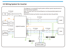
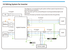
View attachment 132199
According to what you are saying (CT clamp in the service area), this would work and still achieve zero export and yet power the home loads. This does not compute to me, however I am a noob in this ...
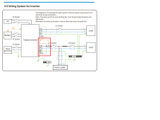
View attachment 132200
anything the ct read at the service area the Deye inverter will support the whole house load, it will act like a grid tie inverter, it will push power thru the grid input of the Deye and the output load of the Deye Is always supported, it will act like a back up load when grid is down.
this is diagram is for Zero Export CT

Last edited:
Thanks! That I know, but that means that the CT clamp has to be in between the grid and the house loads. I am not sure what you mean with the service area. Have you seen my last picture in the previous reply? I can only place the CT Clamp inside the inverter, which means that there are NO loads between it and the inverter. Would that even work with "Zero Export to CT"??
Luxpower_Gilbert
Luxpert @Luxpower USA Team
Service area or main service disconnect. CT clamp must be install before the house load(main service panel) from the main service disconnect…
If your main service disconnect is in your main service panel then you can put the ct before the main disconnect. Post some pictures if possible.
If your main service disconnect is in your main service panel then you can put the ct before the main disconnect. Post some pictures if possible.
Last edited:
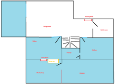
Ok, thought so. Here is a picture, not sure if that helps. Please observe the location of the main panen and the inverter. The spaces in light blue is where I have already a parallel circuit from the AC out of the Easun and the subpanel. Of course I have grid power in all spaces, and the workshop. To connect the CT clamp behind the main service panel, I would need to traverse the kitchen, bathroom with the two wires required by the CT clamp, or go somehow around the house on the exterior. There's no issue in drilling a few holes as I did for the AC out, however these are hidden by furniture or nicely hidden in the flooring sides. The living room, kitchen, bathroom is tile flooring, bathroom is full tiles up to the ceiling. So, I do not really have a convenient way of connecting the CT clamp before the main panel.
I could connect the clamp probably somewhere in the kitchen, on the main circuit, I guess that would be equivalent to connecting behind the main panel with a subset of the loads being monitored by the inverter ...
If I would place the CT clamp right at the inverter location and use "Zero export to Load", could I achieve the current setup? Output only on the current areas via the parallel circuit aka a direct replacement of the Easun? Yes, the house will not be covered fully, yet it will be not worse than the current setup. The reason for going for the Deye for me, is the following: dual mppt, better quality of product, warranty and passive cooling (probably less idle consumption during the night). The other benefits are marginal for me: the fact that this unit needs to use a CT clamp is a disadvantage. The Easun/Growatt and similar do not need a CT clamp, yet they need a parallel circuit.

Luxpower_Gilbert
Luxpert @Luxpower USA Team
Yes it would drop in with your current set up with the ct clamp on wire of grid input. But your missing a good feature of the Deye. If you can get the ct on the main that would be good it can read the whole house load, which can be set to partial or full cover the load by deye…
Your better solution with current set up would have just buy a stand alone mppt charge controller which is way cheaper in my opinion…
Your better solution with current set up would have just buy a stand alone mppt charge controller which is way cheaper in my opinion…
Yes, that was also another option, however that would only charge batteries, yet it will not supply power from the PV to the loads, unless it's a parallel unit, same as the current one.
For instance: I do not know what happens when I split my current panels in two strings, half would be connected to the inverter directly and half to the new mppt. There would be enough PV power to power the loads, but not only with the panels connected to the Easun AOI. The AOI would then try to get the power from the battery, which the other mppt tries to charge. I guess, since it's DC, the current from the mppt would also be used by the AOI, regardless if it would come from the battery or the addional mppt.
For instance: I do not know what happens when I split my current panels in two strings, half would be connected to the inverter directly and half to the new mppt. There would be enough PV power to power the loads, but not only with the panels connected to the Easun AOI. The AOI would then try to get the power from the battery, which the other mppt tries to charge. I guess, since it's DC, the current from the mppt would also be used by the AOI, regardless if it would come from the battery or the addional mppt.
Similar threads
- Replies
- 0
- Views
- 45
- Replies
- 2
- Views
- 144
- Replies
- 5
- Views
- 391
- Replies
- 0
- Views
- 122


