diy solar

diy solar

Review of attached off-grid design appreciated

Frank Enstine

New Member
Joined
Feb 25, 2022
Messages
28
PDF attached

I think my design makes sense, but then I think it can’t be this straightforward and I must be missing some very important considerations. Your corrections/suggestions are greatly appreciated.

I live up north and can have 10-12 days a year in single digits (F). The application is off-grid, primarily back up power with a periodic secondary use case. My peak sun is 2-5 hours.

So, I’m considering an Epever 5420AN charge controller rated for 1250 watts (max 1875 watts), 200 Voc, 50 amps. Among panel options I’m considering are four 320 watt panels from Renogy rated for 32.7Vmp, 40.1Voc, 9.79A Imp. My PV wire run is <=100 feet.

Please help me see the errors of my way…

A 4S arrangement = 1,280 watts, 9.79A, 160.4Voc; 10 AWG @ 100’ = 1.3% drop. I’m not sure if I should be using the Voc or optimum Vmp (to calc the drop) which = 32.7 x 4 = 130.8V. That result would be 1.55% drop. The online calculator I used has a default power factor of .85, not sure if I should adjust that. Could I use 12AWG?

As far as charging current goes with the 4S array after the 1.3% drop, 1,263/28.2=44.8 charging amps. Is 28.2V the right charge voltage for a 24V LiFePo4 battery? Do I need to add a margin of safety and is that a problem for a 50 amp controller?

Am I correct that, in ideal conditions I could charge my 100Ah battery bank in just over two hours and at 72% of max charge current (32A) I could charge a nearly depleted battery bank in 3 hours.

Thoughts on the Epever controller and the Renogy panels? Alternatives?

Thank you all for supporting dummies like me.
 

Attachments

  • Design.pdf
    143 KB · Views: 20
The ac charger circuit should be 12 awg pure copper with 105c insulation and a 20 amp fuse.
Actually all the wires should be pure copper with 105c insulation.
The buck converter circuit should 12 awg with a 20 amp fuse on the 24 volt side and 8 awg on the 12 volt side.
You don't need a fuse on the pv string but it won't hurt.
You don't need a means of disconnect on the system side of the solar charge controller because you have one on the pv side.
The inverter circuit should have a fuse for fault isolation.
Suggest you bump the main circuit to 2 awg and 200 amp fuse to aid in fault isolation.
Since the scc circuit is 4 awg you may as well put a 150 amp fuse on it to consolidate the bill of materials and minimize the number of spares you need to keep.
 
Last edited:
Only a couple thoughts to throw at you:

I live up north and can have 10-12 days a year in single digits (F)
Are you going to be able to keep your batteries above freezing or do they have low-temp cutoff? Charging LFP's below freezing is a "Bad Thing"

There are multiple threads about fusing, but a common item is using Class-T fuses for LFP batteries, NOT the ANL, so you might want to swap that out.

I’m not sure if I should be using the Voc or optimum Vmp (to calc the drop)
Always use VoC when calculating, it gives you more fudge factor. Also, the wire cost should be negligible so I'd stick with 10AWG, it also buys you expansion in the future.

My peak sun is 2-5 hours.
That winter sun is going to hurt, good to see the extra charger in there. I assume that'll be fed by a generator?

Other than that it looks pretty good. Simple is always a good thing, it minimizes trouble later. :)
 
Are you going to be able to keep your batteries above freezing or do they have low-temp cutoff? Charging LFP's below freezing is a "Bad Thing"

There are multiple threads about fusing, but a common item is using Class-T fuses for LFP batteries, NOT the ANL, so you might want to swap that out.
I can keep the batteries warm, I don't think my generator can deliver sufficiently clean power. I bought the AC charger to bridge the gap until I buy the PV array. The inverter has a 4000 watt surge capability which is why I thought the slower ANL was appropriate.
 
The ac charger circuit should be 12 awg pure copper with 105c insulation and a 20 amp fuse.
Actually all the wires should be pure copper with 105c insulation.
The buck converter circuit should 12 awg with a 20 amp fuse on the 24 volt side and 8 awg on the 12 volt side.
You don't need a fuse on the pv string but it won't hurt.
You don't need a means of disconnect on the system side of the solar charge controller because you have one on the pv side.
The inverter circuit should have a fuse for fault isolation.
Suggest you bump the main circuit to 2 awg and 200 amp fuse to aid in fault isolation.
Since the scc circuit is 4 awg you may as well put a 150 amp fuse on it to consolidate the bill of materials and minimize the number of spares you need to keep.
Thanks. I will follow your advise. I have 2 AWG from WindyNation but went down to 4 because my design requires a few sharper bends that favor the smaller gauge. It seem appropriate from what I read. Am i missing something? I have not acquired the other gauges yet but will get the right insulation.

The location of the SCC fuse should be at the SSC and not the bus bar. Correct?
The inverter fuse should be 150A for 4 AWG or 200A for 2 AWG. Correct?
 
The ac charger circuit should be 12 awg pure copper with 105c insulation and a 20 amp fuse.
Actually all the wires should be pure copper with 105c insulation.
The buck converter circuit should 12 awg with a 20 amp fuse on the 24 volt side and 8 awg on the 12 volt side.
You don't need a fuse on the pv string but it won't hurt.
You don't need a means of disconnect on the system side of the solar charge controller because you have one on the pv side.
The inverter circuit should have a fuse for fault isolation.
Suggest you bump the main circuit to 2 awg and 200 amp fuse to aid in fault isolation.
Since the scc circuit is 4 awg you may as well put a 150 amp fuse on it to consolidate the bill of materials and minimize the number of spares you need to keep.
Should the fuses be ANLs or another type?
 
Thanks. I will follow your advise. I have 2 AWG from WindyNation but went down to 4 because my design requires a few sharper bends that favor the smaller gauge. It seem appropriate from what I read. Am i missing something?
Not sure what you are asking here.
The location of the SCC fuse should be at the SSC and not the bus bar. Correct?
Nope it should be as close to the busbar as possible.
The idea is fault isolation.
The really angry pixies come from the battery.
The inverter fuse should be 150A for 4 AWG or 200A for 2 AWG. Correct?
150 amp and 4 awg for the inverter circuit.
 
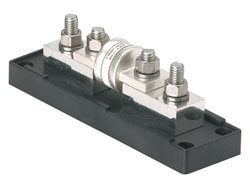
This is a fused busbar.
It enforces best practices.
 
The fuse on the battery circuit should be as close to the positive terminal as possible and should be class t.

I’m adopting all your advice, upgrading wire sizes, locating all fuses at the bus bar. I already own the bus bars and the Victron is quite pricey against my blown budget

I assume the AC charger should have a 20 amp fuse like the 24v-12v converter but I haven’t figured out what to buy. Recommendation?

I’ll update my schematic soon, maybe it will be helpful to other noobs like me. Thanks so much for your help
 
Last edited:
You're going to get pointed to something with a reputable quality like the Blue Sea Class-T and holder.

*Link is for style reference, you'll need to find the right actual size.
I read the description of one I selected wrong, both are for a 3/8” battery stud and mine are 5/16ths. Suggestions?
 
Last edited:
I’m adopting all your advice, upgrading wire sizes, locating all fuses at the bus bar. I already own the bus bars and the Victron is quite pricey against my blown budget

I attached two photos of fuses…
—the 150A ANL I already own. Will this work for the inverter and another the SCC assuming I stick w/4 AWG?
4 awg with 150 amp fuse for the inverter circuit and 4 awg with 150 amp fuse for the inverter circuit.
Double check that the mechanical terminals on the solar charge controller can accept 4 awg.
If not report back on the largest size that it can accept.
—the bolt-on 200A class-T for the main fuse is in my Amazon cart. Is this a good choice?
That is a marine rated battery fuse not a class t.
Very nice fuses but not appropriate for this use because its AIC=arc interrupt capacity is too low for a 200 amp hour 24 volt battery.
I assume the AC charger should have a 20 amp fuse like the 24v-12v converter but I haven’t figured out what to buy. Recommendation?
The 12 awg feeder wire gets a 20 amp fuse.
You can use an inline automotive style fuse in an inline holder for this one.
Just make sure the holder is rated for at least 20 amps.
 
Can you include a product link or picture for the buck converter?

The shunt power circuit also needs a fuse.
 
The concept from orbit is...

Every positive wire off of the busbar needs a fuse.

You have 5 branch circuits and 1 feeder circuit.

The branch circuits should be fused as close as possible to the busbar to isolate faults to a single branch circuit if possible.

The feeder circuit should be fused as close as possible to the battery positive to prevent Armageddon.

We put the big expensive class t fuse on the battery circuit to protect the circuit with the angriest pixies. It is also the backup for the branch circuit fuses in case one of them fails to isolate a fault.
 
The feeder circuit should be fused as close as possible to the battery positive to prevent Armageddon.
Okay, I penciled that onto my drawing earlier but to the bus bar. Should I fuse it off the main fuse instead? The wire run will be less than 2 feet and its max consumption is 12.0 mA.
 
Okay, I penciled that onto my drawing earlier but to the bus bar. Should I fuse it off the main fuse instead? The wire run will be less than 2 feet and its max consumption is 12.0 mA.
I guess you are talking about the shunt power circuit.
It needs a fuse appropriate for its wire guage.
The master fuse should be upstream of every other fuse.
If it blows everything else should be disconnected.
 
I guess you are talking about the shunt power circuit.
It needs a fuse appropriate for its wire guage.
The master fuse should be upstream of every other fuse.
If it blows everything else should be disconnected.

It's Official, You're a Rock Star!!!

I attached my updated schematic, of course I messed something up. All wire length measurements are max, and many may be 1/2 of what's noted. I think I added all yours and Rednecktek's recs
 

Attachments

  • Design2.pdf
    161.1 KB · Views: 11
It's Official, You're a Rock Star!!!

I attached my updated schematic, of course I messed something up. All wire length measurements are max, and many may be 1/2 of what's noted. I think I added all yours and Rednecktek's recs
The closer the main fuse is to the battery positive the better.
Can you not get closer than 18"?
If that 18" wire detached from the fuse it could short directly to the negative terminal of the battery which makes for a very bad day.
 
Back
Top