diy solar

diy solar

Revo II tripping breakers when 2 or more are in use

I have 64 280AH batteries with their own BMS. How do I hook them up so that each Revo is pumping current in them?

I had a week of no sun and the Revo II was pulling current from the grid like I wanted.
I use a lot of power with all the aircondioners, lights etc. Ive seen it go up to 15kw when i was using just 3 units.

I Have 4 Revo II's.
Each one has its own solar array hooked up to it.
How does the power from other units go into the master unit to charge batteries?

There is no master for charging.

64 X 280Ah, probably S16 setup.

I guess you made 4 x S16, with 4 x Negative "controlled" by its own BMS.
And 4 positive.

There is absolutely no reason to not connect all 4 positives and all negative together.

Just hook them up together.
Just try to use the same length of cable between each S16.

Looking at your pictures and way you setup, you probably have the cells directly under the Revo II.

You simply parallel them after the BMS.

Each BMS still controls it's own "unit", and if one cell of that unit have a problem that requires the BMS to act, you have no longer 64 cells connected, but 48.
(The BMS disconnect 16 of the whole set)

I assume you that you have BMS that have mosfet switch to turn of the connection between inverter/MPPT and battery
As it's hybrids, I assume you use common port BMS.
(One port for charge and discharge)

Each Revo II does its own thing.
It's important to fine-tune the Revo II to have matching settings.

They all might see slightly different voltage readings from the total battery.
Unit one sees 53.2 volt, unit 2 sees 53.2, unit 3 sees 53.4 and unit 4 sees 53.3v.

Slight difference, but important to set at the battery voltage settings.

The standard "lithium" settings for the Revo are higher then I prefer.

To get the Revo in Lithium settings, you first set each unit into lithium battery option.

Safe and exit the settings menu.
I personally like to reboot to make sure it's saved.

After this you go to user Battery setting, and set the charging voltage.

For me I have both the same at 54.7v
That works for me.
When the sun goes down and the battery starts to get used, the voltage indication shows about 85-90% charged.

I have my cut off voltage relative low.
The few times I might get to that low level, I probably need it, and draining to 2.5 (or below, as long as you stay above 2v per cell) is not really destructive. Under 2 volt you lose a few cycles.
Over 3.65... you lose a lot of cycles..
Way more destructive.

Anyways, those are mine settings.

The Revo II is on paper capable of 4500 watt solar panels, max open voltage 450v.
If you feed it more then 5200 watt it goes into protect mode, waits some time to cool down and restarts the MPPT.

I can't advise to feed it over 4500W, as long as you stay under 5000W.. you are normally in the clear.

You probably have seen the maximal charge settings of solar and grid.
Older versions of the firmware it's "limited" to, if I recall correctly, to 60A, together max 90A
Newer version can do 90A for solar.

That is the left over energy to put into the battery.

If you are using 1000 watt, andd your solar panels produce 5000 watt, you have 4000 watt to charge the battery with.
Probably +53 volts, is 75A.

The Revo II goes in steps of 10A.
Then 70A would be the best setting.
80A would push you beyond the 5200 watt.. :)

For the battery array, once you confirmed the voltage it reads,you set the charge accordingly.

The 53.2v both have the same, like mine both at 54.7v (bulk and float)
The 53.4 would be 54.9, and the 53.3 would be 54.8v as maximal charge voltage.

It's not bad if one unit stops charging a little sooner then the others, or starts later / earlier.

It's an ongoing flow process, always in movement, never exact values.

Stopping at 85-90% works for me, and I have the crazy hope that what people write, getting the extra cycles is reality with my setup and my cells.
Even if it doesn't, I get "just" the 2500 cycles... I'm happy.
I don't need to charge to 100%.

For imbalance, yes,from time to time probably.
I use active balancer, same as the active Balancer BMS, without the BMS part.

I now use the DIYBMS.
 
Sharing one other experience so you won't have to...

The solar +/- is "HOT"...
If at night you play around with the cables, and you happen to grab the negative solar lead from the inverter... You get a 450v surprise.

I did not try of the positive will give the same breat taking experience.

It hurts.. a lot.

When ever doing maintenance, discharge the capacitors!

When you open the unit, close to the top left you see two screws.
(Bus- and bus+)
Use a resistor between them to discharge.
Internal bus voltage is 450v (?, Or close to)

View attachment 28064

I have shocked myself with the units. One of the units was not using any PV power and beeping with a code. I already have another board from Sorotec to replace the bad unit
 
There is no master for charging.

64 X 280Ah, probably S16 setup.

I guess you made 4 x S16, with 4 x Negative "controlled" by its own BMS.
And 4 positive.

There is absolutely no reason to not connect all 4 positives and all negative together.

Just hook them up together.
Just try to use the same length of cable between each S16.

Looking at your pictures and way you setup, you probably have the cells directly under the Revo II.

You simply parallel them after the BMS.

Each BMS still controls it's own "unit", and if one cell of that unit have a problem that requires the BMS to act, you have no longer 64 cells connected, but 48.
(The BMS disconnect 16 of the whole set)

I assume you that you have BMS that have mosfet switch to turn of the connection between inverter/MPPT and battery
As it's hybrids, I assume you use common port BMS.
(One port for charge and discharge)

Each Revo II does its own thing.
It's important to fine-tune the Revo II to have matching settings.

They all might see slightly different voltage readings from the total battery.
Unit one sees 53.2 volt, unit 2 sees 53.2, unit 3 sees 53.4 and unit 4 sees 53.3v.

Slight difference, but important to set at the battery voltage settings.

The standard "lithium" settings for the Revo are higher then I prefer.

To get the Revo in Lithium settings, you first set each unit into lithium battery option.

Safe and exit the settings menu.
I personally like to reboot to make sure it's saved.

After this you go to user Battery setting, and set the charging voltage.

For me I have both the same at 54.7v
That works for me.
When the sun goes down and the battery starts to get used, the voltage indication shows about 85-90% charged.

I have my cut off voltage relative low.
The few times I might get to that low level, I probably need it, and draining to 2.5 (or below, as long as you stay above 2v per cell) is not really destructive. Under 2 volt you lose a few cycles.
Over 3.65... you lose a lot of cycles..
Way more destructive.

Anyways, those are mine settings.

The Revo II is on paper capable of 4500 watt solar panels, max open voltage 450v.
If you feed it more then 5200 watt it goes into protect mode, waits some time to cool down and restarts the MPPT.

I can't advise to feed it over 4500W, as long as you stay under 5000W.. you are normally in the clear.

You probably have seen the maximal charge settings of solar and grid.
Older versions of the firmware it's "limited" to, if I recall correctly, to 60A, together max 90A
Newer version can do 90A for solar.

That is the left over energy to put into the battery.

If you are using 1000 watt, andd your solar panels produce 5000 watt, you have 4000 watt to charge the battery with.
Probably +53 volts, is 75A.

The Revo II goes in steps of 10A.
Then 70A would be the best setting.
80A would push you beyond the 5200 watt.. :)

For the battery array, once you confirmed the voltage it reads,you set the charge accordingly.

The 53.2v both have the same, like mine both at 54.7v (bulk and float)
The 53.4 would be 54.9, and the 53.3 would be 54.8v as maximal charge voltage.

It's not bad if one unit stops charging a little sooner then the others, or starts later / earlier.

It's an ongoing flow process, always in movement, never exact values.

Stopping at 85-90% works for me, and I have the crazy hope that what people write, getting the extra cycles is reality with my setup and my cells.
Even if it doesn't, I get "just" the 2500 cycles... I'm happy.
I don't need to charge to 100%.

For imbalance, yes,from time to time probably.
I use active balancer, same as the active Balancer BMS, without the BMS part.

I now use the DIYBMS.


Im using the Chargery BMS. The chargery and Revo use the same RS232 communication cable to talk with each other.
Im planning on stopping charge at 85% and putting cells in a compression block.
And yes im going to have the cells below the units.

I have 12-390 watt panels hooked to each of 3 units so a total of 36 panels. The 4th unit has 12-335 watt panels. I was using a midnite classic 200 and would always see around 3600 watts out of the 335 watt panels. I have never come close to that power output in full sun with the revo and the 390s. Dont know if the solar guys wired something off or not. They did have to rewire it because voltage was way too high as they wired 12 in series and the panels are 48.48 volts i think it is. Q panels duo series. So it was 6 in series and 2 in parallel.
So far all this seems very complicated. Wish someone was close by that i could pay to finish it all out. Lol
 
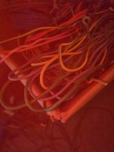
The white neutral wire you see in the first pic went to nothing. It was just a loose wire they ran in the box hooked to nothing.
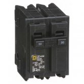
The red and green both were going to the hot legs on the 220 volt breakers. On the AC/IN from the grid.
Im going to post more pics of their wiring down below
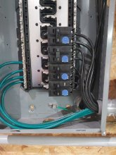
From left to right. First Set of 3 wires is the AC/In from the grid green/ground Black/ hot red/ hot. The 2 hot wires are directly to the 30 amp breakers and the green is to the grounding bar in the breaker box.
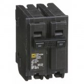
Next set of 3 wires is the AC out feeds a 50 amp double pole breaker. green 10 guage wire is the ground black/hot 6 guage black/hot guage 6 guage. Yes they had mismatched wire size.

View attachment 28077View attachment 28078

The first pic in my OP was wiring of my solar installer.
2nd pic was my wiring with the trough. 2 black wires are hot to both legs of the double pole breakers.

This is my job I did. I followed the same wiring sequence the solar guys did. Ground hot hot on both the AC in and AC out. Lowes was out of a lot of wire so I had to made do with what they had.

The black and red on far right is the PV. Its clearly marked on the Revo of which is + and -

View attachment 28079View attachment 28080
Personally, I NEVER use the same colour for neutral and hot.

Neutral is black (or brown), hot is blue.
Ground yellow/green.
(Black is often used as switching cable for lights in AC)

For DC black is negative, red positive.

Easy to make mistakes.
With consequences you don't want.

If you have both black..
One next person who might think you "know what you are doing" will expect it's "safe" to hold the black, neutral wire......
Or the green/yellow.

Here in Thailand they usually don't give a -peep-
What ever colour is available they use.
And if they make wrong connection, they get shocked or the breaker flips ( or both)

Ground wire can be a really thin wire.
It's just to release enough leaking current to trip the safety.
Most people use the same thickness as the AC wires.

Here, green/yellow can be life wire...

Back to your setup.
If it's not too much trouble, change the life wire for a blue one, or make many blue/red tape marking on the "L" line
Black / brown is good for "N" neutral,
Geen or green/yellow for the ground.
Also white and gray is used for this.
(To keep life simple)

Just as long as you use the same colour for the whole setup.
Not gray and green....
 
Im using the Chargery BMS. The chargery and Revo use the same RS232 communication cable to talk with each other.
Im planning on stopping charge at 85% and putting cells in a compression block.
And yes im going to have the cells below the units.

I have 12-390 watt panels hooked to each of 3 units so a total of 36 panels. The 4th unit has 12-335 watt panels. I was using a midnite classic 200 and would always see around 3600 watts out of the 335 watt panels. I have never come close to that power output in full sun with the revo and the 390s. Dont know if the solar guys wired something off or not. They did have to rewire it because voltage was way too high as they wired 12 in series and the panels are 48.48 volts i think it is. Q panels duo series. So it was 6 in series and 2 in parallel.
So far all this seems very complicated. Wish someone was close by that i could pay to finish it all out. Lol
Thailand close enough :)

Lol

Sorry, not for all the money in the world would I leave Corona free Thailand to visit any other country at this time.

I have COPD, burned both lungs badly at the age of 16..
Now 52 and already 15 years "incapacitated", my energy level fluctuate, a lot.
I can do anything, just can't tell when we it will be ready.
What used to take a day is now quickly a week or a month...

I gave my father advice on how to deal with less energy after he had Hart problems at 79...

I'm not complaining.
But Corona probably will be fatal for me.

Video calls work great, and I can talk you through the process.

Still start with using the correct colour codes, and stick with them!

I don't like pure green as in some (low) light it can look like blue..
The "L" life or load wire..
And not safety ground....
 
IMG_20201120_201234_copy_1200x1600.jpg

Just to give you an indication how wires look like in low light.

You know, the time you are fixing a problem you didn't know you where going to have..
At night.

This is blue, green, red and green/yellow.

The last 2 are clearly different.
Blue and green....
That is already getting challenge.
(My camera clearly repairs the colours...The blue almost looks like "red" In real life it's hardly distinguished
 
Last edited:
Where does that white neutral wire in the upper picture go in the inverter? Where in your house?
I see red and black hots, and green ground connected. Other group same inverter, two black hots (ought to use colored phasing tape), and green ground.

Lower picture has two black hots and green ground, two black hots and white neutral. Is that a second inverter in the system?

Pretty sure you've got a 220V only European model here.

Obviously if you lose track of the two phases (usually red & black) and parallel two inverters feeding through power from the grid in such a manner that you short he phases together, a breaker is going to trip (best case)

If you're lucky the 220V "hot" and "neutral" are floating so they don't mind being pulled to +/-110 or +/-120 still within spec.
But once you disconnect from the grid you'll have floating 220 coming from the (battery powered) inverter a what voltage the two hots have with respect to neutral will depend on the load.

If you have a 110V 100W bulb on each phase, 220V applied to two identical bulbs will light both perfectly. If you have a toaster and a bulb, you'll be enjoying un-toasted bread in the dark.

But if you're lucky and it can provide floating 220V, adding a balancing transformer on the output (two 120V windings appropriately wired in series), that could make a neutral voltage right in the middle. Ground that and you're good, up to the VA rating of the transformer.


I did have the units built for US specs. When I had 3 of them running i was turning stuff on and had 2-4.5 ton AC units running just fine along with several 1500 watt appliances, the well and some lights. The watts being used on the 3 units totaled close to 15,000 watts. Power was being used by solar and AC in from the grid in combination with one another.
I know the installers were looking at the symbols behind the wiring inputs and said it was Euro wiring symbols but it didnt matter.
 
View attachment 28081

Just to give you an indication how wires look like in low light.

You know, the time you are fixing a problem you didn't know you where going to have..
At night.

This is blue, green, red and green/yellow.

The last 2 are clearly different.
Blue and green....
That is already getting challenge.
(My camera clearly repairs the colours...The blue almost looks like "red" In real life it's hardly distinguished


I can see where in low light, colored eye glasses or a filter on a light can change the color of items. I can always use colored tape.

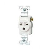
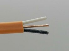
Here in the US we use 10/2 wire if hooking up a 220 volt plug on a 30 amp double pole breaker.

The white and black wires both go to the legs of breaker and the outlet. The bare copper wire is run to the grounding bar in the breaker box and to the brass colored ground on the outlet. _20_amp_220_volt_657574393.jpg

s-l400-2.jpg
 
So what you saying is that all the right hand side of the AC out on the Revo needs to be on the top leg of the breaker and All the middle black wires need to be on the bottom leg of the breaker and the green wires just on the grounding bar?

I always thought one leg was 120 and the other leg was 120 thats what meter shows.

I use the 50s on the AC out and the 30s on the AC in from the grid.
Z_-ut-fo5oy.JPG.jpgZ_-utxfo5oy.JPG.jpg


Here is a pic of them in the breaker box.

Z_-ut-fo5oy.JPG.jpgZ_-utxfo5oy.JPG.jpg20201116_153351.jpg
 
I can see where in low light, colored eye glasses or a filter on a light can change the color of items. I can always use colored tape.

Here in the US we use 10/2 wire if hooking up a 220 volt plug on a 30 amp double pole breaker.

The white and black wires both go to the legs of breaker and the outlet. The bare copper wire is run to the grounding bar in the breaker box and to the brass colored ground on the outlet. View attachment 28087

View attachment 28086
Not insulated wire for grounding is good.
No risk on making mistake :)
Or you feel (or are afraid to feel) directly.
Perhaps even better then green/yellow.

"Europe" (or the other 2/3th of the globe) uses ground, neutral and load.

One should never use the same colour for neutral and load.

For me, I don't "care" about how it's done in the USA/Canada/ south America, the rest of the globe has this standard, and like many have told it's not really compatible.

Best to keep "Western" (?) Wiring at the Western Revo II units upto the conversion box to make it into "other half" idea of electricity.

Living in Thailand, traveling to Many, many countries, I have seen a lot of counties outside "Europe* to have this 220-240 volt system.
UK 240 volt, the rest 220.
It stings to call it "Europe way", when more then 2/3th of the globe uses that system.

For me USA is odd way.
For you this is odd way.

What ever it is, it's not really compatible as is.
That it worked can be called a wonder, stretching the limitations of the Revo II.
(Who can do 184-265VAC output range, and accepts 120-280VAC input)...

While in a "twisted way" possible to use, it's for sure not recommended.
There are many terms used like split phase (??) I'm "USA style" of electricity, that "Europe style" never heard of it is compatible with.

The only good advice in can give is make the setup as it's intended.
"Europe style".
Then, as you have different, incompatible system, use the intended converter to convert between the 2 incompatible systems.

This way you stay within specifications if the inverter and your local rules and regulations.

You probably lose a few %, but it's the only recommendable and safe way to do.

All others is abusing the wide range to make it fit for "USA style".
Wide range available as not all generators will provide stable grid, or even grid to be stable.

We (Thailand) have spikes and dept's... 170-250v.
Thrust me, many power supplies (like inside TV) don't like to be chocked with 170v..

Many people use grid balancers, out of need.

For those fluctuations the Revo II have wide range of voltage...
Not to force it into "USA system".

No disrespect, I find it really smart that it was able to work at all.
It's for sure not recommended or intended.

Revo II is probably not the best hybrid inverter for USA Canada and south America, when you are connected to a grid.

How did you end up with the Revo II units?
Did you buy them?
Or was it in a house you bought?
Just curious.
 
So what you saying is that all the right hand side of the AC out on the Revo needs to be on the top leg of the breaker and All the middle black wires need to be on the bottom leg of the breaker and the green wires just on the grounding bar?

I always thought one leg was 120 and the other leg was 120 thats what meter shows.

I use the 50s on the AC out and the 30s on the AC in from the grid.
View attachment 28088View attachment 28089


Here is a pic of them in the breaker box.

View attachment 28088View attachment 28089View attachment 28090
I don't know USA style of breaker.

One side have 220-240, depending on the settings, the other..
You can grab with your hand, no problems. 0 volts.

(Measure between ground and N / L)
Between N and L you have also 220-240v.

If you have anywhere 120...
That is not coming from the Revo, probably your grid.
It can "eat" 120v but not spit it out.

There is no 120 volt with the Revo II at all.
 
I did have the units built for US specs. When I had 3 of them running i was turning stuff on and had 2-4.5 ton AC units running just fine along with several 1500 watt appliances, the well and some lights. The watts being used on the 3 units totaled close to 15,000 watts. Power was being used by solar and AC in from the grid in combination with one another.
I know the installers were looking at the symbols behind the wiring inputs and said it was Euro wiring symbols but it didnt matter.
The inverters should run your 240V loads just fine, connect to two hot legs.
When on-grid, the input will be +120V/-120V (at one instant in time; because it is AC it will later be -120V/+120V)
Off grid, because the grid's hot wires are disconnected and the grid's neutral isn't used for load side, the output could be +120/-120 or it could be +240/0 (and later -240/0 as AC cycles) or float anywhere else.
The 240V loads will still work fine.

What won't work is 120V loads.

I see you connected a bunch of green wires in the box to a busbar, and one smaller green to a lug on the sheetmetal enclosure. Are those ground wires from the inverters?

We treat "neutral" and ground differently. White for neutral, green or bare for ground, each with its own wire. They only join together at one place, typically in the box with utility meter. That is because we don't want current from appliances going through the ground wires.

Do you have 120V loads on the output of the inverters? They connect to one hot and the neutral (also to ground). If their neutral connects to neutral from grid, they will get 120V while grid is connected through inverters. If their neutral connects to ground, they will get 120V while grid is connected and they will send current through ground. If a ground wire becomes open circuit, the chassis of appliances will have 120V and be a shock hazard.

When inverters disconnect from grid, any 120V appliances will not have a fixed voltage. They will see anything from zero to 240VAC, may burn up, may experience brownout and burn up.

The only way you can use these inverters to power 120V loads is if you add a transformer. It would be an auto-transformer with two 120V windings connected in series, so with 240V applied to the outer pair of leads and center-tap grounded you get +120V/zero/-120V.

I think your system, if it has any 120V loads attached, is a safety hazard because an open ground wire doesn't simply mean ungrounded equipment chassis, it means electrified equipment chassis.

I think your system will kill 120V loads. Maybe not immediately, it depends on what combination of loads are attached where.
 
Hedges and I are on the same page here. Those units will only work to sell power back to the grid. IF you bond your AC output loads panel then your going to have real issues because the neutral no longer floats. It will be tied to the ground which is 0 volts. (ground loop discussions aside) Your output will then always be 0v on N and +240v on L.

As to your original question, you still need to indicate which black wires are going to which locations on the breakers. get some colored tape, mark each wire at the N connection at the inverter, and then mark the other side of that wire. All those taped wires, need to go to the same side of their breakers (could be top or bottom doesn't matter the important part is they are consistent for all the units)

@Hedges I don't think brushed motors are safe on his 0-+240v system if it was off grid. As I recall the winding layout is designed that its expecting the field to flip 180 deg. If the voltage never goes negative when the brushes hit the other half of the winding the field will not have changed direction and the armature is not pulled through another 180 of rotation. (my brain can't reconcile if this spins or just results in a locked rotor condition)

That and half of everything in the house wont work because L2-N is 0-0 volts. Even if the panel is not bonded, all you need is for one manufacture to intentionally or unintentionally have N and G bonded and you have a 0 reference for the entire system. (so I think you have to assume its 0-240v N-L1)

Don't worry about brush type motors, induction motors, resistive loads, or anything else 240V. All they care about is relative voltage between the two wires. Doesn't matter if one is grounded and the other swings between +240 and -240, or if one is +120 and other -120, then they swing to -120 and +120. Motor still sees 240Vrms AC.

He doesn't have one leg grounded and the other leg hot for +/-240V. He has two hot legs, neither grounded, coming out two poles of a breaker. L1 to L2 is 240V. While on grid, L1 to N is +120V, L2 to N is -120V (and half a cycle later voltages reverse.) But off grid, voltage to neutral or ground isn't fixed. Depends on loads.

All he needs to do is:
Carry green ground through from grid to inverters, to chassis of breaker panel, to ground pin of sockets.
Carry white neutral through from grid to neutral bar of breaker panel.
Do NOT bond neutral to ground. That only occurs at grid connection by utility meter
Add a transformer to breaker panel, which will maintain relative voltage of L1, L2, N

That should work fine unless transformer is overloaded and overheats, or trips as breaker disconnecting it. Then neutral is undefined again. Best to have a transformer large enough to handle 100% of power from all inverters, taking in 220V from all of them and delivering it entirely to an imbalanced 110V load. Or put only 240V loads on that panel. If you want a few 120V loads, put them on a separate panel fed by transformer and shut off if transformer overheats or trips its breaker.
 
Still curious..
"Build for USA style",or your words :
"I did have the units built for US specs."

Who built them that way?
Sorotec?
Or the installer?

I mean, if it's Sorotec, all should be fine, and the specifications I know off are meaningless, as it's special build product by the manufacturer.

Kevin, Eurus and Ella are really knowledgeable people about their product and should be the ones you should talk to for this installation.

Knowing how they helped me, all is good and you should be up and running in no time.

If it's the "electrician" who told;
"I know the installers were looking at the symbols behind the wiring inputs and said it was Euro wiring symbols but it didnt matter."
....

They where full of crap and sold you BS.....
They magically twisted the specifications to make it working in USA grid system.
Magic you can't re-create.

You should talk to them to to the installation again and probably, the defective unit....
Got fried due their magic.

So I'm curious!!

I could ask Sorotec,and if they did costum build for you, you are already in contact with them..
If not..
The installers screwed you over.
Get atleast for free the conversion unit for 20kw from those guys.

You could get their license for installing unqualified material this way.

I really hope for you custom made product by Sorotec.
 
Not insulated wire for grounding is good.
No risk on making mistake :)
Or you feel (or are afraid to feel) directly.
Perhaps even better then green/yellow.

"Europe" (or the other 2/3th of the globe) uses ground, neutral and load.

One should never use the same colour for neutral and load.

For me, I don't "care" about how it's done in the USA/Canada/ south America, the rest of the globe has this standard, and like many have told it's not really compatible.

Best to keep "Western" (?) Wiring at the Western Revo II units upto the conversion box to make it into "other half" idea of electricity.

Living in Thailand, traveling to Many, many countries, I have seen a lot of counties outside "Europe* to have this 220-240 volt system.
UK 240 volt, the rest 220.
It stings to call it "Europe way", when more then 2/3th of the globe uses that system.

For me USA is odd way.
For you this is odd way.

What ever it is, it's not really compatible as is.
That it worked can be called a wonder, stretching the limitations of the Revo II.
(Who can do 184-265VAC output range, and accepts 120-280VAC input)...

While in a "twisted way" possible to use, it's for sure not recommended.
There are many terms used like split phase (??) I'm "USA style" of electricity, that "Europe style" never heard of it is compatible with.

The only good advice in can give is make the setup as it's intended.
"Europe style".
Then, as you have different, incompatible system, use the intended converter to convert between the 2 incompatible systems.

This way you stay within specifications if the inverter and your local rules and regulations.

You probably lose a few %, but it's the only recommendable and safe way to do.

All others is abusing the wide range to make it fit for "USA style".
Wide range available as not all generators will provide stable grid, or even grid to be stable.

We (Thailand) have spikes and dept's... 170-250v.
Thrust me, many power supplies (like inside TV) don't like to be chocked with 170v..

Many people use grid balancers, out of need.

For those fluctuations the Revo II have wide range of voltage...
Not to force it into "USA system".

No disrespect, I find it really smart that it was able to work at all.
It's for sure not recommended or intended.

Revo II is probably not the best hybrid inverter for USA Canada and south America, when you are connected to a grid.

How did you end up with the Revo II units?
Did you buy them?
Or was it in a house you bought?
Just curious.


I bought 5 of the units. Use 4 and keep one as a spare in case something goes south.
 
The inverters should run your 240V loads just fine, connect to two hot legs.
When on-grid, the input will be +120V/-120V (at one instant in time; because it is AC it will later be -120V/+120V)
Off grid, because the grid's hot wires are disconnected and the grid's neutral isn't used for load side, the output could be +120/-120 or it could be +240/0 (and later -240/0 as AC cycles) or float anywhere else.
The 240V loads will still work fine.

What won't work is 120V loads.

I see you connected a bunch of green wires in the box to a busbar, and one smaller green to a lug on the sheetmetal enclosure. Are those ground wires from the inverters?

We treat "neutral" and ground differently. White for neutral, green or bare for ground, each with its own wire. They only join together at one place, typically in the box with utility meter. That is because we don't want current from appliances going through the ground wires.

Do you have 120V loads on the output of the inverters? They connect to one hot and the neutral (also to ground). If their neutral connects to neutral from grid, they will get 120V while grid is connected through inverters. If their neutral connects to ground, they will get 120V while grid is connected and they will send current through ground. If a ground wire becomes open circuit, the chassis of appliances will have 120V and be a shock hazard.

When inverters disconnect from grid, any 120V appliances will not have a fixed voltage. They will see anything from zero to 240VAC, may burn up, may experience brownout and burn up.

The only way you can use these inverters to power 120V loads is if you add a transformer. It would be an auto-transformer with two 120V windings connected in series, so with 240V applied to the outer pair of leads and center-tap grounded you get +120V/zero/-120V.

I think your system, if it has any 120V loads attached, is a safety hazard because an open ground wire doesn't simply mean ungrounded equipment chassis, it means electrified equipment chassis.

I think your system will kill 120V loads. Maybe not immediately, it depends on what combination of loads are attached where.


Yes those 4-6 guage green wires are from the 4 inverters. Each one has its own ground running to the ground bus bar.
Each unit also has its own 10 guage green wire that attaches to the ground bus bar in the AC/In aka grid current.

The small green wire thats attached to the breaker box I believe is going to a ground rod outside. It does not go to the inverters.

Their is no 120 volt loads from the inverters they are 240v only.
240v in from the grid
Solar PV array in. 390-410 volts
240v out.
The 240v out goes to its own breaker box that feeds the house, shop etc.

I have 2 breaker boxes everywhere. 1 for grid and one for solar. All i have to do flip some switches and run completely off of grid power or completely on solar power.
They are all 240 volt subpanels/breaker boxes

Out of these subpanels aka breaker box you can run 120volt appliances. These subpanels have 2 legs in them and both are 120v. Just have get a single pole 20 amp breaker and run some 12/2 and wire in the outlets that the appliances plug into for power.


Here is a video on how U.S. current works. Im not real sure on just 1 wire being 240.

 
picard-meme-facepalm.jpg
 
I have 2 breaker boxes everywhere. 1 for grid and one for solar. All i have to do flip some switches and run completely off of grid power or completely on solar power.
They are all 240 volt subpanels/breaker boxes

Out of these subpanels aka breaker box you can run 120volt appliances. These subpanels have 2 legs in them and both are 120v. Just have get a single pole 20 amp breaker and run some 12/2 and wire in the outlets that the appliances plug into for power.
All sounding good except:

1) Flip switches to select grid power or solar power - are those interlocked to prevent every connecting both at the same time? Because if that happens, possible outcomes are:
a) Inverter gets smoked
b) Breaker trips
c) Utility worker is electrocuted

2) If you try to run 120V appliances off two hots from a 220V inverter and a floating neutral, bad things happen:
a) Something gets smoked
b) Something gets brownout, then maybe smokes

You can fix (1) if you use an interlocked main/backfeed breaker. I've installed interlocks in existing panels, and bought generator interlock panels which came pre-wired that way.

You can fix (2) if you add a transformer to create a neutral half way between voltage of the two 220 legs. It should be wired back to neutral coming from utility, so it is good whether running things on or off grid.
 
Still curious..
"Build for USA style",or your words :
"I did have the units built for US specs."

Who built them that way?
Sorotec?
Or the installer?

I mean, if it's Sorotec, all should be fine, and the specifications I know off are meaningless, as it's special build product by the manufacturer.

Kevin, Eurus and Ella are really knowledgeable people about their product and should be the ones you should talk to for this installation.

Knowing how they helped me, all is good and you should be up and running in no time.

If it's the "electrician" who told;
"I know the installers were looking at the symbols behind the wiring inputs and said it was Euro wiring symbols but it didnt matter."
....

They where full of crap and sold you BS.....
They magically twisted the specifications to make it working in USA grid system.
Magic you can't re-create.

You should talk to them to to the installation again and probably, the defective unit....
Got fried due their magic.

So I'm curious!!

I could ask Sorotec,and if they did costum build for you, you are already in contact with them..
If not..
The installers screwed you over.
Get atleast for free the conversion unit for 20kw from those guys.

You could get their license for installing unqualified material this way.

I really hope for you custom made product by Sorotec.


Sorotec built them when I messaged them through Alibaba and asked if I could purchase 5 of them. They said they would and asked what I wanted. The installers did not get them I did. They had never installed a hybrid inverter before. Not many people around here have hybrid or even off grid systems most do grid tie and that is what they do.

Eurus is the one I have been communicating with and some of the questions he asked was.

1. Voltage and frequency input/output 220 VAC, 50HZ correct?
2. product SOROTEC logo or neutral without any logo?
3. user manual: english type, neutral without any logo
4. package carton: neutral without any logo
5. for the lable, use our model number
6. any other request pls let me know


Those are his exact questions.


I told him this

1. 240 volts and 60 hertz
2. Sorotec Logo or none is fine. It doesn't matter to me
3. English. Logo doesnt' matter
4. Whatever is the easiest for you guys and most secure
5. Yes that will be fine
6. I don't have any request but if you have any more questions just let me know.


That is directly from my email exchange between them.
 
Back
Top