Bleedingblue
Solar Enthusiast
- Joined
- May 12, 2020
- Messages
- 557
Turn off all Revo inverters except the master.I put on the communication cables today and tried them and still same result. Even had error pop up on communication. I emailed the company
What you should be able to see is that when disconnected from the grid and running off batteries the Revo inverter produces 220V (or 240V if that was the customization.) But you should be able to see that it does not produce 120V.
All good so far. You have 248V coming fro grid through inverter to loads.
Turn off all Revo inverters except the master.
Connected to grid, measure voltage on the panel L1 to L2, L1 to Ground (or neutral), L2 to Ground (or neutral)
Then disconnect from grid and take those measurements again.
Then connect a lightbulb between L1 and Ground (or neutral) and take the measurements again.
Just what I expect.Ive ran just off solar and it puts out 240
All good so far. You have 248V coming fro grid through inverter to loads.
And it may well say that, under no load.Ok ill try that tomorrow when I get home. But i know from a multimeter it says 124
And it may well say that, under no load.
Try powering a single 120V 100W incandescent light bulb from one phase of Revo inverter output, with grid disconnected.
Then measure the voltage.
And nothing wrong with that, no danger to utility worker if this inverter implements UL1741. Although, it may not have received independent testing and certification which would confirm it performs active anti-islanding. Without certification it is best to keep it set for zero export, just supporting your loads.This is what the screen looks like if im feeding the grid.View attachment 28127
We may yet find that the vendor built a split-phase unit for you, with the ground symbol for the center tap.
That will kind of sort of work, but has some issues when wired back to grid because it will send imbalanced currents over ground.
Just a possibility they did that.


Like to see the schematic, from inverter to 120V panel to loads. And ratings of loads.I know its powering some appliances lights etc because I did that earlier today.
And nothing wrong with that, no danger to utility worker if this inverter implements UL1741. Although, it may not have received independent testing and certification which would confirm it performs active anti-islanding. Without certification it is best to keep it set for zero export, just supporting your loads.
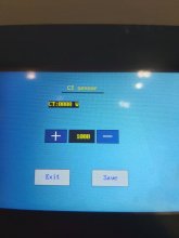
CT sensor may be Current Transformer sensor, so it can backfeed to the house but not so much it backfeeds through the meter.It does have some features I dont know what it does.
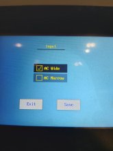
View attachment 28131View attachment 28132View attachment 28134
Like to see the schematic, from inverter to 120V panel to loads. And ratings of loads.
I could make it work, and I could make it fail.
I did such stuff as a child, modifying the wiring of my mom's house (with power on).
I did burn out some things in the process.
I also started a kitchen fire, cracked a window with an explosion, crashed a variety of motorized and unmotorized vehicles, ate things I shouldn't have, provoked a dog to put four holes in my head, many other incidents I somehow survived.
CT sensor may be Current Transformer sensor, so it can backfeed to the house but not so much it backfeeds through the meter.
Useful stuff when net metering is not allowed.
But I want to get your setup working so current is never carried in green (ground) wires, and so it delivers steady 120V to 120V loads rather than voltage which could kill them.
It's a matter of using the right color wire in the right place.I could check tomorrow and see if their is current going through my ground wire. I might have to drive in another ground rod. I'm fixing to go to bed right now as I have to get up early for work. Talk to you tomorrow.
Thanks for your input
Also measure resistance between input/output grounds, input/output N, input/output L1Since you have a 5th inverter not hooked up, check resistance between ground/N/L1 of input and output. Want to see if there is any galvanic connection from current carrying terminals and ground. There is an off chance they wired a 120/240V transformer and put the center tap on the screw called ground.


