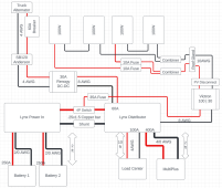
Hi guys, I'm looking for some feedback on upgrading my RV rooftop solar system. Our current system is 4x100W Renogy panels wired in 2s2p with a disconnect and 40A Renogy charge controller connected to the (1x 100Ah AGM) battery w/ a fuse.
We're upgrading to a mostly Victron system with more batteries and an inverter. I'm also adding 30A alternator charging via a 120A-rated Anderson connector and Renogy DC-DC charger.
The Renogy panels and disconnect will remain for now. I will probably repurpose the existing renogy charge controller to use a ground deploy array to add another 200-400W of PV. Our main goal is to increase our battery capacity and add an inverter to power the coffee pot, microwave, computers, and monitors for a few days while off grid.
Main Components:
Batteries: 2x LiTime 230Ah LiFePo4 (200A BMS)
Inverter: Victron MultiPlus-II 2x120
DC-DC Charger: 30A Renogy DC-DC Charger
PV Charger: Victron Smart Solar 100 | 30
Description:
The LiTime batteries are connected in parallel via a Lynx Power In with 2/0 AWG cables, and 250A fuses. I'm not really sure about this wire/fuse size, as I can't find a lot of specs for systems paralleled on the bus bar rather than at the battery, but in my head each should be getting about half the load? The batteries will only be about 1-2ft from the Power In.
The Lynx Distributor is connected to the DC-DC charger (8AWG / 60A fuse), the RVs existing 12v load center (4AWG / 100A fuse), and the MultiPlus (4/0AWG / 400A fuse) per the manufacturer recommendations. The MultiPlus will only be a few feet from the distributor, while the load center is probably be 10ft.
4x 100W Renogy panels are wired in a 2s2p configuration using the existing RV roof entry gland. The cables are connected to a DPDT PV disconnect. That feeds to a Victron SmartSolar 100 | 30 charge controller. All of that is done with a combination of 8 and 10 AWG cables (10AWG is built in the RV and 8AWG is what I've added). PS I know the fuses are unnecessary, but I added them a few years ago for whatever reason.
The Power In is connected to the Distributor with a 500A Victron Smart Shunt on the negative side, and a 500A rated BlueSea 4 position battery switch on the positive. The switch has "off", "1", "2", "and "1+2" positions and "Input 1", "Input 2" and "Out" terminals. My plan is that the Power In will be connected to Output, the Distributor to Input 1, and the PV charger to Input 2. I believe that this will allow:
- Off: Total disconnect of batteries.
- 1+2: "Normal" operation. E.g. Batteries are connected to loads, and the PV charger is connected to batteries.
- 1: Run 12v loads while disconnecting the PV system (e.g. if maintenance is required).
- 2: Disconnect loads, and charge via PV (e.g. for when RV is in storage).

Last edited:


