


Nobodybusiness
Collecting the leftovers of the Great Sky Reactor.
I was trying to upload a video and realized I can’t so made some screenshots.
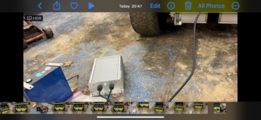
I am using the original Ryobi Charger. It’s 7.5 amps.
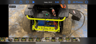
JK 150 amp BMS.
The interlock still works.
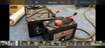
Literally pulled out the AGMs.
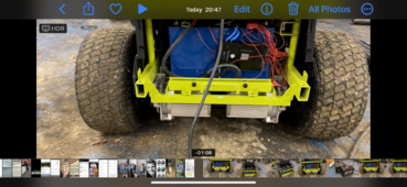
Put in 16 280ah LIFEPO4 and it works great.
The original battery charge indicator Meter on the side panel works fine also.
I use the JK BMS app anyway for charge level.
It took me about 5 hours to do by myself mainly because of Trying to situate the batteries but they fit fine in the tray.
With the top bar screwed down in the middle of the pack it’s solid
Edit:
After Supervstech suggestion I’ll put in a pre charge resistor.
I am using the original Ryobi Charger. It’s 7.5 amps.
JK 150 amp BMS.
The interlock still works.
Literally pulled out the AGMs.
Put in 16 280ah LIFEPO4 and it works great.
The original battery charge indicator Meter on the side panel works fine also.
I use the JK BMS app anyway for charge level.
It took me about 5 hours to do by myself mainly because of Trying to situate the batteries but they fit fine in the tray.
With the top bar screwed down in the middle of the pack it’s solid
Edit:
After Supervstech suggestion I’ll put in a pre charge resistor.
Attachments
Last edited:
