DanTheEnergyMan
New Member
- Joined
- Apr 25, 2021
- Messages
- 3
Hi everyone ?
I've been working on an electrical diagram for my van, and all the parts have arrived; now I'm just after a quick safety check since I'm a total noob and don't want to blow myself up.
Questions/Concerns
Thank you anyone who gave time to review/read, it is very much appreciated. Vector diagram attached below as well if the photo is blurry.
Please let me know how badly I've done") it only took me a year to learn this all
it only took me a year to learn this all

I've been working on an electrical diagram for my van, and all the parts have arrived; now I'm just after a quick safety check since I'm a total noob and don't want to blow myself up.
- Solar: 1.2kW (3x400w panels in parallel)
- 70v Voc; 6.5A Isc;
- Apparently no need for individual fusing in Australia because (number of panels - 1 * Isc) < 20A (max series fuse) for these panels, so 3 in parallel is okay. They're in parallel because solar charge controllers get expensive higher than 70Voc.
- Charge controller is a 100v-50A Victron MPPT - so should be maxed out by the panels during the day in "sunny hot australia".
- Battery: 6kWh of LiFePo4 cells at 24v (8S configuration) (cells from Amy - Shenzhen Luyan)
- BMS is a Electrodacus SBMS0; no MOSFETS. Excited to try this out, I don't see many people using it.
- Inverter: 3kW Multiplus II for AC; 70A charging
- Bus Bars: BlueSea MaxiBus 250A
- 24/12VDC converter: Victron 20A non-isolated
Questions/Concerns
- Grounding; I've read/watched plenty of stuff, but I'm still confused on what I should do!? ?
- My understanding is I'll ground the battery to the chassis; and everything with a ground connection I'll connect to the chassis as well; no ground-return in the system, everything goes back to the negative bus-bar.
- So for example, if a fault occurs in the fridge, the fridge frame may become live, but is grounded to the van wall so becomes the negative conductor in this case, back to the battery; allowing the circuit to complete and the breaker to trip?
- I'm still reading up more on this, trying to get a fundamental understanding...
- I chose to use circuit breakers for all the all the main components - is this okay?
- Reasons for using circuit breakers:
- As a noob, I wanted quick and easy isolation between solar/battery/inverter should something go wrong; so instead of buying a fuse+holder+high-amp switch, I just got circuit breakers instead.
- I also chose double pole circuit breakers for most things (except AC circuit) because they were similar price; and the noob inside said total isolation is better than half isolation for some reason.
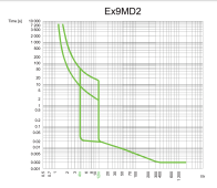
- I'm worried these won't trip fast enough if a "not high enough current" fault occurs. Because of the time/current trip curve of the breakers; if a 500A fault occurs instead of 900A fault (for example), then the 160A breaker won't trip for 60 seconds - which seems bad. Basically I'm banking on a fault being a big fault and not a little fault. Thoughts? The large circuit breakers are Noark Ex9MD1B (125A, for inverter) and Ex9MD2B (160A, for battery).
- Reasons for using circuit breakers:
- Only low voltage disconnect for AC circuit
- So the BMS doesn't have mosfets, meaning disconnection is on me. However, at 25V I don't want to to kill everything; I want to put the inverter into Charger mode (via remote switch, I think this is possible with the SBMS/Multiplus, I'll figure it out); so killing AC power is okay - but;
- I don't want to kill ALL 12v/24V loads - I guess I really want 4 DC distributions; 12V essential, 24v essential; 12v non-essential; 24v non-essential
- Screw that lol it's just a van. I'll sound an alarm on my phone or something when battery gets low I think (I'll figure this out okay) .... is this okay? I'm guessing people usually just have all loads turned off because the BMS stops it... hmm.
- Otherwise I'll buy a Victron battery protect or something and do the same as the inverter, remote switch, and if anything is really essentialy, hopefully it's 24V and I'll wire it straight to the busbar or something.
- Surge Protection/Lightning Protection
- It doesn't seem too common to install these things; should I add them?
Thank you anyone who gave time to review/read, it is very much appreciated. Vector diagram attached below as well if the photo is blurry.
Please let me know how badly I've done
it only took me a year to learn this all