robert272727
New Member
Hi all. Im looking on google and can find answer. Have DEYE 3 phase hybrid invertor + seplos mason with 280ah EVE cells. CAN communication and all in default. After charge to 100 percent during the day and sun power is more as for house so I have feeding to grid, even that it starts to discharge battery with around 2,5 amps until 97% SOC, it takes about 3 hours, then it charge again to 100%...and again go to 97%SOC.... In my case battery is never in state of idle....
When there is not enough power from sun it discharge battery properly to cover the house.
Please is this normal, or is this problem of deye invertor or seplos bms?
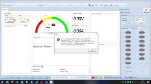
this is Im talking about - 153wats / 2,5 amps is going out from batt after fully charged.... even house don't need it...

Thanks
When there is not enough power from sun it discharge battery properly to cover the house.
Please is this normal, or is this problem of deye invertor or seplos bms?
this is Im talking about - 153wats / 2,5 amps is going out from batt after fully charged.... even house don't need it...
Thanks
Last edited: