diy solar

diy solar

Settings for Victron SmartShunt 500/50mv

DixieMtCR

New Member
Joined
Jan 28, 2021
Messages
135
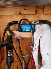
I have a smart shunt in my solar power system to keep track of my batteries. I get alarms from the app saying that the battery voltage is too low. The problem with that is that the shunt is telling me that it's sitting at a state of charge of 96%. Bring up the app and sure enough my battery voltage is low.

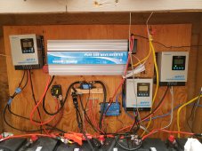
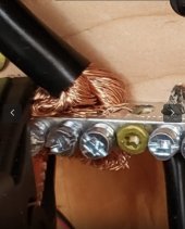
I have 8 lead acid sealed batteries which are RV deep cycle batteries 100 ampere hours each. They are wired in two series four parallel to form a 24v bank. The batteries are only about a year and a half old. I have taken the system apart and measured the voltage of each battery and the batteries are good. When the sun is shining I get really good charging. And when it's cloudy days or totally clouded over or at night it would seem that there's about 2 1/2 amps of quiescent current being pulled out of the batteries. It's quite possible that the inverter and the network access point are pulling that. But overnight the system should not drain down to less than the kickout voltage just having an access point and the inverter.

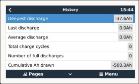
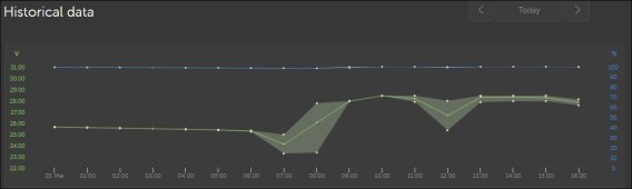
Using the data from the Victron Cerbo GX I really don't see anything that could drain such a huge battery bank overnight. What is going on with this thing does anyone have an idea?

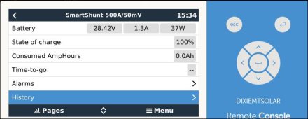
Last night the batteries were 100% SOC. This morning at 7:34am, they were at 99% (which is ok) but the voltage was 23.55v. The Smart Shunt was reporting that it had used 12.1Ah over night.

12Ah in that big of a battery bank should not bring that voltage down that low?

By the way, all of the panels have been tested to see of the diodes are blown. They all tested good. No leaking
 
Can you send a screen shot of your Victron settings?
What is the voltage of the individual batteries?

Sounds as if you may need to reset the Victron once it hits 100%.

If The batteries are at 23.55, then they sound as if they are fried? Could be one all of mine. What is the set uo for th batteries? I assuming 2S4P.
 
You are likely having false sync events especially if charging with solar.

For lead acid:

Charged voltage: 0.2V below absorption voltage for solar or 0.2V below float for shore/generator charging.
Tail current: 3%
Peukert: 1.25
Efficiency 95%
 
Your SmartShunt is reporting the 100% incorrect.

Your batteries are at 100% SOC if the voltage is at 28.8 V for at least one hour while charging.

And have your SmartShunt settings like @sunshine_eggo said
0AF9EF83-0254-480A-AAEA-BB8506FA813D.jpeg

And change the SOC to 30% when the voltage is at 23.55 V or so.
74F26E07-B1A8-470C-85CF-2A84DC6824C8.jpeg
 

Attachments

  • 23AA732F-A247-451D-A4A1-6ED5419088C7.jpeg
    23AA732F-A247-451D-A4A1-6ED5419088C7.jpeg
    32.3 KB · Views: 6
Last edited:
Can you send a screen shot of your Victron settings?
What is the voltage of the individual batteries?

Sounds as if you may need to reset the Victron once it hits 100%.

If The batteries are at 23.55, then they sound as if they are fried? Could be one all of mine. What is the set uo for th batteries? I assuming 2S4P.
Well, it has been about a month since I tested the batteries. If I remember correctly, with the batteries all disconnected from each other, they were about 13.8v plus or minus a tenth.

The batteries are configured 2s4p, as you have said.

Right now the remote console says the batteries are at 100% at 28.42v, as seen in the attached photo
 

Attachments

  • remote console now.JPG
    remote console now.JPG
    43.4 KB · Views: 6
You are likely having false sync events especially if charging with solar.

For lead acid:

Charged voltage: 0.2V below absorption voltage for solar or 0.2V below float for shore/generator charging.
Tail current: 3%
Peukert: 1.25
Efficiency 95%
I am charging with solar. Here is a description of the system.

I have three solar panel racks.
Each of the solar panel racks are approximately 600 watts each. Two of the racks have six 100 Watt panels and the third one has two 320 Watt panels.
The 600 watt panel racks are wired 3S2P. Reasoning here is to get the voltage up high enough to where the charge controllers can work on cloudy days in Oregon.
The 640 Watt rack with the two panels is wired 2p.

Each of the panel racks feed its own charge controller. They are 40 amp MPPT charge controllers.

Each of the charge controllers is connected to the battery bank.

Per instructions each of the components that use power or make power are connected to the smart shunt on the negative side. The negative side of everything must go through the shunt.

I have a 4000 Watt pure sine wave inverter connected to the battery bank which is also connected through the shunt on the negative side.

I have a victron cerbo gx connected to the shunt and also to a wifi AP thru an ethernet cable, so the stats can be read remotely through the VRM.

All three panel racks are tilted at 45 degrees this time of year, and facing solar noon south. I live just above the 45th parallel In western oregon.
 

Attachments

  • more of smartshunt.JPG
    more of smartshunt.JPG
    36.8 KB · Views: 7
When the sun is shining at noon plus or minus, it is not uncommon to see the charge controllers putting out 17-20amps each when the microwave along with all the other lights in the house are on. I have 10 circuits in the house load center that run through a manual transfer switch. Any or all of the 10 can be switch to solar at any time, manually.

This is an off-grid system to provide basic electricity when the grid goes down (often) in winter, and when the grid/power company shuts off the power to the area in summer when the fire danger is high with high temps and low humidity. We live very rural in Oregon.
 
More information. In the attached graph from the VRM, how can the system be at 100% if the voltage dips to nearly 23v?

See attached chart
 

Attachments

  • Historical data now.JPG
    Historical data now.JPG
    36.1 KB · Views: 8
If the batteries were at 200% and were under sudden load, the voltage would drop and recover, such as a electric motor starting.

My next guess would be the setup of the batteries. These are a bad setup
690F0F8B-2CDC-4C2A-B678-A82A1007B9E6.jpeg0B627990-9AC3-41E7-A8FC-66D6C91D88BC.jpeg
Better
44670D5C-4B85-41C8-B4D9-1DEF7CCCBF9F.jpeg
And bestest
2517A557-8323-45C1-83C8-3B5B431C11B5.jpeg
I will vouch for @sunshine_eggo who helped me set up a Victron shunt by direct message a few months ago.
 
When you share your VRM site on VRM world we can all have a look at your data without disturbing any of the settings.

Read more about this feature on VRM world.

Here’s an example from Andy in Australia

900B8CAF-01A8-4595-BCE3-2EA12EE5C627.jpeg
 
Last edited:
OK, looks like I might have the VRM World share set up.

ON the dashboard and the advanced screens, you will see that I had the battery charger from the grid connected so that the batteries would be fully charged.

At 8:13 am this morning I turned off the grid powered battery charger and the solar took over. It has been charging ever since. Not much though. It has been snowing most of the day.

Victron says the Regulated Absorb Charge voltage for 24v batteries should be between 28.2 volts and 29.4 volts. They also say that the Regulated Float Charge Voltage should be between 27 volts and 27.6 volts. The fluctuations that are seen in the screens are do to those times when the sun attempts to shine and then is covered again.

The only things that effect the charge voltages are the settings on the charge controllers.

NONE of the 10 Transfer Switch circuits are turned on. The only drain on the batteries would be the quiescent current of the 4000w PSW Inverter, the Cerbo GX, and the Pepwave Surf SOHO AP that I use to connect the ,Cerbo GX to the house Wifi.

Currently, the Cerbo GX is only monitoring the SmartShunt 500. I have no idea how to connect any of the other ports on the Cerbo GX to do further monitoring.

The link to myVRM-World is here. Keep in touch. I can make changes
 
Under Remote Console, update your log interval:

Settings -> VRM Online Portal -> Log Interval -> 1 min

You can also track by the second within VictronConnect and the Trends option:

1679872706348.png

The smartshunt will retain these data for 45 days.
 
One basic question. Look at the battery- is the only wire/cable from the battery negative connected to the shunt? There are no other wires on any negative battery or on the battery lug of the shunt - right??? All charging and discharging is going through the “load” side of the shunt.

The reason for the question is I have seen something new get added right to the battery. Then all the shunt data is off because of a wiring error.
The charge controllers have a negative wire. That wire is connected to the bus that shown in the picture.

As you can see in the attached photo the negative clip of the battery charger that is connected to the grid is also connected to the common negative which is on the utility side of the shunt. The shunt is the only device in this setup that is connected to the negative terminal of the battery Bank.
 

Attachments

  • 16798749565027803013802650785647.jpg
    16798749565027803013802650785647.jpg
    174 KB · Views: 31
  • 16798751402432289017757148297776.jpg
    16798751402432289017757148297776.jpg
    303.3 KB · Views: 30
Sorry but I don't have a screen that looks like that and so I don't know how to get out of those parameters to list them or change them

Advanced tab.

Should be here:

1679875311185.png

The charge controllers have a negative wire. That wire is connected to the bus that shown in the picture.

As you can see in the attached photo the negative clip of the battery charger that is connected to the grid is also connected to the common negative which is on the utility side of the shunt. The shunt is the only device in this setup that is connected to the negative terminal of the battery Bank.


Your wiring looks correct.

Again, please post VictronConnect settings.

Check the following on remote console:
  • Back at your Cerbo you have to do the following three things:
  • Go to SETTINGS > VRM ONLINE PORTAL > ENABLE TWO WAY COMMUNICATION
  • Go to SETTINGS > GENERAL > REMOTE SUPPORT and ENABLE REMOTE SUPPORT
  • Go to SETTINGS > REMOTE CONSOLE > ENABLE ON VRM
  • This requires a reboot of the Cerbo. Go to SETTINGS > GENERAL > REBOOT
 
Last edited:
Back
Top