Well your avatar says you're a solar saucer So you might be able to find out what that looks like in that picture period obviously that big cable has braided wire and it's too big to go into that bus period so the braids were split into two braids and put into two slots of the bus.Ummmm what, the what?
You are using an out of date browser. It may not display this or other websites correctly.
You should upgrade or use an alternative browser.
You should upgrade or use an alternative browser.
Settings for Victron SmartShunt 500/50mv
- Thread starter DixieMtCR
- Start date
I will catch you guys later tomorrow sometime. Thanks for all your hard work and all your suggestions. I'm done for the day. It's dark it's cold and it's snowing like crazy outside and I really don't have much interest in going out there a hundred feet out into the yard to a cabinet that I can't get inside. I open the doors on it and I have to kneel out there in the snow with the snow falling and work on electrical stuff and it just doesn't make much sense so I will take a look at that stuff tomorrow and see if I can figure out how to get into that menu structure that one of you is talking about. The only way I can get out my shunt while in the house is through the victron vrm. But I really can't get at the shunt I can only get at the things that the serbo GX sends to me. You see the Bluetooth on the smart shot is so wimpy that I have to stand six to eight feet away from it at most so that it will communicate with my phone. That's junk. So I had to buy the c e r b o GX to communicate with the smartshunt. What a fun way to spend money. In my retirement. All right got you guys tomorrow if you're around have a good one.
I was just thinking if you’ve been able to drop the coin for almost 2-3k in solar gear/batteries, I think some $40 bus bars and proper lugs wouldn’t break the bank.Well your avatar says you're a solar saucer So you might be able to find out what that looks like in that picture period obviously that big cable has braided wire and it's too big to go into that bus period so the braids were split into two braids and put into two slots of the bus.
Those “bus bars” look like neutral bars from a service panel, any idea if you know the current rating of those?
If you have 1800w of PV you have about ~60a of PV possibly going through those “bus bars” during peak solar, let alone the possible draw of the 4K inverter if you push it to nameplate (~140-160a) which I’m sure you aren't even close to. I’d be suprised those bus bars are rated any where close to that.
Inter connections of equipment and cheating out on small parts has been the source of many many issues people seem to face here. Also those “pop style” “breakers” are another source of huge head aches. When large currents are involved proper connections are key for moving current without voltage drop and increased losses.
Last edited:
sunshine_eggo
Happy Breffast!
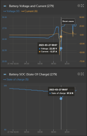
Shunt is clearly tracking usage.
The question again becomes what are your shunt settings (for the third time).
FWIW, you can use victronconnect through VRM and shouldn't have to trek out to the shed.
Open VC
select the VRM tab
Select the Cerbo
select the devices tab
Select the shunt and open the settings normally. There is a short initial lag compared to direct access via bluetooth.
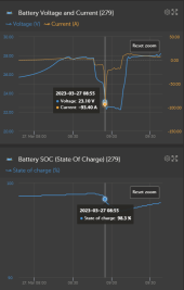
What the hell are you using to hit this battery with ~100A?
Pim57
New Member
- Joined
- Mar 10, 2021
- Messages
- 125
Thanks for sharing your VRM site!
My findings:
On March 25 17:12 the battery is really at 100% with 30 V and 1.5 A
Then the next two days the battery is stable with little load/charge.
On March 27 08:30 the battery is at 98.8% with 27.6 V and 2.8 A
then 37 minutes later at 09:07 batt at 97% with 22.3 V and -16.9 A
Now in this 37 minutes time frame something is going wrong.
Good batteries cannot have such big voltage drop from 27.6 down to 22.3 when depleted with 1.8%=7.2Ah.
So either:
A. Your batteries are End Of Life
B. Your cabling has a high resistance
For A. You can check the fluid level in the battery.
For B. You can measure the voltage drop on your cabling while there is a current flowing like 10-20 A.
And last I agree with previous comments that you could do a better job with the cabling.
Rout them nicely in conduit’s, use better busbars and put decent crimp’s on the cables. And while doing so put some labels on.
Last edited:
Seeing it’s rather intermittent, my guess there’s a connection someplace that could use a 1/4 to 1/2 turn.So either:
A. Your batteries are End Of Life
B. Your cabling has a high resistance
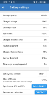
Here are the shunt settings. Thanks for your help in interpreting all this.The question again becomes what are your shunt settings (for the third time).
I see from your profile that you have well over 8000 posts. You must spend a lot of time on here helping people. I would love to spend time chatting, comparing notes, and get everything done when asked. It is just not possible, even in retirement. I don't even own a rocking chair. That is how most people picture seniors. Sitting around watching TV. I don't even have a TV. No reception where we live in the woods of NW Oregon.
Sorry to not get this to you in a timely manner. Your comments about how to connect to the shunt without going out in the snow was most helpful. Lately, I have spent around 4-6hrs a day running a snow blower to keep our access to the county road open. One day, I even had to use the snow blower on 1/4mile of road to open it up so we could get out. No rest.
Again, sorry about the delay in answering.
Thanks for the information on the solar setup. much of that data on charging and usage is "Polluted". Ha Ha. When the battery level gets too low I have been putting my battery charger (Grid Powered) on the system so the batteries will not be ruined by discharging too deep.Thanks for sharing your VRM site!
My findings:
On March 25 17:12 the battery is really at 100% with 30 V and 1.5 A
Then the next two days the battery is stable with little load/charge.
On March 27 08:30 the battery is at 98.8% with 27.6 V and 2.8 A
then 37 minutes later at 09:07 batt at 97% with 22.3 V and -16.9 A
Now in this 37 minutes time frame something is going wrong.
Good batteries cannot have such big voltage drop from 27.6 down to 22.3 when depleted with 1.8%=7.2Ah.
So either:
A. Your batteries are End Of Life
B. Your cabling has a high resistance
For A. You can check the fluid level in the battery.
For B. You can measure the voltage drop on your cabling while there is a current flowing like 10-20 A.
And last I agree with previous comments that you could do a better job with the cabling.
Rout them nicely in conduit’s, use better busbars and put decent crimp’s on the cables. And while doing so put some labels on.
I am using the system even when we do not NEED it. I built it for power outages and those times when we cannot get out of here for gasoline for the generator. Power goes out here often and it usually happens when the snow it deep or it has been very windy and trees are down across the roads.,
Anyway, the information in the charging and usage data may be misleading because it had a mix if solar and grid charging. I deleted the history and for 2 days have been building a database of only solar charging. As you can see today, heavy rain and the heavy cloud cover is keeping the system from even making enough energy to keep the wifi access point and the inverter to power it, alive.
Can't check the fluid levels in the "Sealed Maintenance Free" Deep Deep Cycle 12v RV batteries.
Oh yes, the reason for the deep current pulls at times. They 10 circuits in the house that can be switched over from grid to solar through a Manual Transfer Switch were chosen to power essential circuits in the house in the event of a long term outage. I don't monitor it very closely so sometimes things happen. When I have the 10 circuits on, it includes the kitchen circuits. THe microwave (1100w) is the culprit. When the wife does not know or forgets that I am testing, she sometimes used the microwave. The system can handle it for short times, if the batteries are up and there is sun to recover.
I will measure the voltage drop on the cabling and let you know the results.
Keep in touch.
sunshine_eggo
Happy Breffast!
Here are the shunt settings. Thanks for your help in interpreting all this.
I see from your profile that you have well over 8000 posts. You must spend a lot of time on here helping people. I would love to spend time chatting, comparing notes, and get everything done when asked. It is just not possible, even in retirement. I don't even own a rocking chair. That is how most people picture seniors. Sitting around watching TV. I don't even have a TV. No reception where we live in the woods of NW Oregon.
Sorry to not get this to you in a timely manner. Your comments about how to connect to the shunt without going out in the snow was most helpful. Lately, I have spent around 4-6hrs a day running a snow blower to keep our access to the county road open. One day, I even had to use the snow blower on 1/4mile of road to open it up so we could get out. No rest.
Again, sorry about the delay in answering.
Well, assuming you truly have 400Ah of battery capacity and you're only using ~17Ah/day:
(400-17)/400 = 96%, and the shunt reads about 97%, so nothing egregious there.
I now have to concur with some of the other observations that there appears to be a problem with your system - most likely bad/aged/worn out batteries or connections.
See @Pim57 post:

Settings for Victron SmartShunt 500/50mv
Ummmm what, the what? Well your avatar says you're a solar saucer So you might be able to find out what that looks like in that picture period obviously that big cable has braided wire and it's too big to go into that bus period so the braids were split into two braids and put into two slots of...
Here's why:
I concur on the observation of that bus bar. I was simply looking at what was wired to the shunt. It likely needs to be replaced with a suitably rated bus bar.
- It's time to brave the weather and make the trek out there to check each and every connection in the system. They should be torqued to spec.
- All cables should be inspected that the shrink is not pinched between the cable terminal and the battery terminal.
- No washers are in between any connections - they should only be used immediately below the nut.
- You need to check the individual 12V battery voltages. I suspect that some of them are over voltage and others are under voltage. Best to check them when at peak voltage (28.4V per VRM) and a low voltage (22-23V-ish). It's critical that both batteries forming a single 24V are the same voltage.
@chrisski has posted a good bit of info on wiring the bank. Here is the minimum you need:
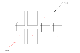
If you don't have it wired similarly or BETTER than the above, your bank has no hope of being reasonably load balanced.
Yes, the bus bars are neutral bus bars from a load center. It is what I had at the time to make it all work, going into winter. They will be replacedI was just thinking if you’ve been able to drop the coin for almost 2-3k in solar gear/batteries, I think some $40 bus bars and proper lugs wouldn’t break the bank.
Those “bus bars” look like neutral bars from a service panel, any idea if you know the current rating of those?
in time and when money permits.
I realize that 2-3k is a chunk of change to spend on solar. Solar is NOT a viable solution in NW Oregon. These are the problems. Low sun angle in fall, winter, spring. Large Old Growth Trees that shade the property most of the day. All of the day in winter. NW Oregon has little potential for solar even if the trees are not in the way. At the best time of year, I only have usable sun from 8-5 daily. We can literally go for a couple of months or more between Nov and Mar that we never actually see the sun. Clouds, rain, snow, fog (clouds on the ground at 1450ft elevation) and angle. The solar angle here is december is 21degrees above the horizon. My solar racks are on wheels so I can roll them around the yard in the day to get what sun is shining when it does. No sun on the panels Dec-Jan. Front yard is 100ft by 250ft. That helps.
Oh, btw, I am retired (10yrs) and the 2-4k is not to total expense of this needed project. and, it did break the bank. So, 40 bucks here and there has to be budgeted. Yeah, I know, too much information. But I realize that solar will NEVER pencil out here in NW Oregon. Arizona, you bet.
Each of the 8 batteries (Exide Brand) wired (2s4p for 24v system) are 100Ah Deep Cycle 12v RV batteries. Half of them are 1.5years old. The other half are 1yr old. (I had the capacity to charge more batteries so I bought more.) They were purchased new locally. They are sealed maintenance free batteries. Someone said a few months ago that the batteries could be toast. I shut the system down and disassembled the battery bank and tested all the batteries. They all tested good. All the connectors were cleaned and reassembled. The connections were then coated with battery terminal protection as they were before they were before the testing. I purchased a new battery tester yesterday. I will retest all the batteries again when the weather permits. Pouring rain for the next few days. Oregon!Well, assuming you truly have 400Ah of battery capacity and you're only using ~17Ah/day:
(400-17)/400 = 96%, and the shunt reads about 97%, so nothing egregious there.
I now have to concur with some of the other observations that there appears to be a problem with your system - most likely bad/aged/worn out batteries or connections.
The 4000w PSW inverter puts out 121v. In the summer when we have 8hr a day sun, it is not uncommon to use 7000 to 10000WattHours of energy from the system, and be full when I switch back to the grid. Because the 3 (12v-24v) MPPT 40a charge controllers sit at about 18-20a when there is a demand on the system, the system seems to work at its capacity.
But, I have always been searching for the reason why the systems drains overnight and has even gone into alarm with just a wifi AP connected that runs 24/7.
sunshine_eggo
Happy Breffast!
Each of the 8 batteries (Exide Brand) wired (2s4p for 24v system) are 100Ah Deep Cycle 12v RV batteries. Half of them are 1.5years old. The other half are 1yr old. (I had the capacity to charge more batteries so I bought more.) They were purchased new locally. They are sealed maintenance free batteries. Someone said a few months ago that the batteries could be toast. I shut the system down and disassembled the battery bank and tested all the batteries.
How?
They all tested good.
what were the results?
All the connectors were cleaned and reassembled. The connections were then coated with battery terminal protection
This isn't always a good idea. It depends on the substance.
as they were before they were before the testing. I purchased a new battery tester yesterday. I will retest all the batteries again when the weather permits. Pouring rain for the next few days. Oregon!
Link to the tester?
The 4000w PSW inverter puts out 121v. In the summer when we have 8hr a day sun, it is not uncommon to use 7000 to 10000WattHours of energy from the system, and be full when I switch back to the grid. Because the 3 (12v-24v) MPPT 40a charge controllers sit at about 18-20a when there is a demand on the system, the system seems to work at its capacity.
But, I have always been searching for the reason why the systems drains overnight and has even gone into alarm with just a wifi AP connected that runs 24/7.
IMHO, one or more of the following:
Bad connections (loose, poor quality)
Bad battery configuration (not wired to share current per my sketch or the options listed by @chrisski ).
Battery imbalance (the two 12V in series forming a 24V are not the same voltage).
Batteries shot.
so that you can see where any possible leaks are in the system, the system is not powering the house. The only thing that is now on is the Inverter. I even went outside and disconnected the AP from the inverter and plugged that into the house via an extension cord. So, there are 3 things affecting the battery bank level. 1) Solar charging (none except that we can tell that it is daylight outside.) 2) Current drain. (Inverter is on but nothing is connected to its output. I want to see if it quiescent power drain is more than I can make on a NO SUN day. 3) Leakage and high resistance connections.Well, assuming you truly have 400Ah of battery capacity and you're only using ~17Ah/day:
(400-17)/400 = 96%, and the shunt reads about 97%, so nothing egregious there.
The 17Ah/day that you are seeing is just the quiescent drain of the inverter and the AP.
normally during an "8hr sun day", my 10 120v circuits in the house, will use 7k-10k watt hours according to the meter on the transfer switch. At that time, when I disconnect the house from solar and back to the grid, the system is still reporting 100% charge and consumed ampere hours are 0. FULL!
sunshine_eggo
Happy Breffast!
so that you can see where any possible leaks are in the system, the system is not powering the house. The only thing that is now on is the Inverter. I even went outside and disconnected the AP from the inverter and plugged that into the house via an extension cord. So, there are 3 things affecting the battery bank level. 1) Solar charging (none except that we can tell that it is daylight outside.) 2) Current drain. (Inverter is on but nothing is connected to its output. I want to see if it quiescent power drain is more than I can make on a NO SUN day. 3) Leakage and high resistance connections.
The 17Ah/day that you are seeing is just the quiescent drain of the inverter and the AP.
normally during an "8hr sun day", my 10 120v circuits in the house, will use 7k-10k watt hours according to the meter on the transfer switch. At that time, when I disconnect the house from solar and back to the grid, the system is still reporting 100% charge and consumed ampere hours are 0. FULL!
If you're producing 7-10kWh of solar during that day, then you won't use any battery capacity.
What does it read before you disconnect the house from solar?
Additionally, I didn't mention it before, during troubleshooting, any voltage readings reported by the shunt should be confirmed with a separate voltmeter.
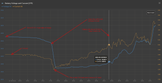
Again, please look at the circled part:
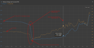
The 2V drop due to an increase in current of 1.5A screams that there is a major connection or battery problem
The capacity is 100% at the time that I disconnect the solar from the house each day. That is what the 10 120v circuits in the house use in that 8hr time period. when I know that it will be a strong sunny day, I turn it on early, maybe an hour or 2 before the sun is on the panels, knowing that it will catch up when the sun hits the panels. The panels produce about 60 amps in full sun. As you can see, I am only producing about 5amps right now, 2 of which is going to feed the hungry inverter. 60 amps is not the case this time of year.If you're producing 7-10kWh of solar during that day, then you won't use any battery capacity.
What does it read before you disconnect the house from solar?
Additionally, I didn't mention it before, during troubleshooting, any voltage readings reported by the shunt should be confirmed with a separate voltmeter.
So, do I hear you saying that the shunt voltage readings could be out of calibration?
The shunt does nothing but measure. But the settings for the shunt can determine the accuracy of the readings that are stored. It appears that the 100% SOC can be set. I have done that a few times when I FELT it was the right moment. But, what determines when I should push the 100% State of Charge Synchronize button? The system is NEVER at a quiescent point with everything connect to where I can definitively say, the battery voltage is 100% and the current is 0, meaning the charge controllers are now still charging.
Zero Current Calibration, in my estimate, can only be done by disconnecting any possible load from it before pressing the Calibrate button.
The question that still haunts me is this. When the SOC says 95%, how can the batteries be depleted? If I have a 400Ah bank that I can use to 50%, then I should have 200Ah usable power. RIght? Is part of the victron system that is doing the math going by the number of Ah used until it gets to an assumed 50% or is it making its calculations on battery voltage at any given time? Obviously, since a shunt is a current measuring device, and the shunt is connected to the "Voltage Level" of the bank, it stores voltage and current readings at the sample rate and the app or the VRM does the math on the the data.
I have some quality multimeters and will take some readings and write them down. I have no history log book of readings. Pretty much all in my head.
Last edited:
As seen in this screen shot, the voltage displayed could be determined as a rising voltage within the BULK charge mode. It is also within the range of the FLOAT voltage range. Bulk is pushing regulated current toward the Absorb voltage level. But, since the Consumed Ah is not zero, I have to assume that the system is in Bulk. There just isn't enough current to push the voltage up to the 28.2 to 29.4 volts that victron specifies on its site to push the charging into Absorb.
If you have been watching the charging of the battery bank today you have noticed that the Consumed Ah has only gone from -16.90 to -8.50 today. Not much charging going on. No sun, not even once for a little while.
I am sure there is some device that Victron has that can be connected to the output of the CC to measure current produced. The shunt only measures net current. Current made minus current used..
The Cerbo GX allows me to monitor the system without sitting on a stool in front of the electronics cabinet in the front yard (watching electrons go by.... or do you count the holes going the opposite direction.) I guess it depends on which way an engineer measures current flow.
Looking at the remote console on the phone app, there is space for other sensors such at AC inputs, AC loads, and of course, it says my system is OFF. Maybe that is my whole problem! How do I turn it on?
I supposed another shunt could be connected in line with the CCs and connected to the Cerbo GX, but I don't know if the Cerbo can facilitate 2.
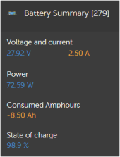
If you have been watching the charging of the battery bank today you have noticed that the Consumed Ah has only gone from -16.90 to -8.50 today. Not much charging going on. No sun, not even once for a little while.
I am sure there is some device that Victron has that can be connected to the output of the CC to measure current produced. The shunt only measures net current. Current made minus current used..
The Cerbo GX allows me to monitor the system without sitting on a stool in front of the electronics cabinet in the front yard (watching electrons go by.... or do you count the holes going the opposite direction.) I guess it depends on which way an engineer measures current flow.
Looking at the remote console on the phone app, there is space for other sensors such at AC inputs, AC loads, and of course, it says my system is OFF. Maybe that is my whole problem!
I supposed another shunt could be connected in line with the CCs and connected to the Cerbo GX, but I don't know if the Cerbo can facilitate 2.

Last edited:
sunshine_eggo
Happy Breffast!
The capacity is 100% at the time that I disconnect the solar from the house each day. That is what the 10 120v circuits in the house use in that 8hr time period. when I know that it will be a strong sunny day, I turn it on early, maybe an hour or 2 before the sun is on the panels, knowing that it will catch up when the sun hits the panels. The panels produce about 60 amps in full sun. As you can see, I am only producing about 5amps right now, 2 of which is going to feed the hungry inverter. 60 amps is not the case this time of year.
If you have a "strong sunny day" where the PV supplies all the energy, then yes, the shunt will correctly read 100% until you draw from the battery.
So, do I hear you saying that the shunt voltage readings could be out of calibration?
I'm saying it needs to be verified.
The shunt does nothing but measure. But the settings for the shunt can determine the accuracy of the readings that are stored. It appears that the 100% SOC can be set. I have done that a few times when I FELT it was the right moment. But, what determines when I should push the 100% State of Charge Synchronize button?
Usually never. If you have the shunt programmed correctly, and it syncs/fully charges at least a couple times a month, it should be accurate enough.
The system is NEVER at a quiescent point with everything connect to where I can definitively say, the battery voltage is 100% and the current is 0, meaning the charge controllers are now still charging.
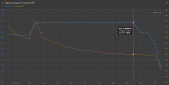
On 3/22, this was certainly fully charged:
Zero Current Calibration, in my estimate, can only be done by disconnecting any possible load from it before pressing the Calibrate button.
Correct. You could disconnect everything from the system side of the shunt. You can also verify the current measurement with a clamp DC ammeter if you have one.
The question that still haunts me is this. When the SOC says 95%, how can the batteries be depleted? If I have a 400Ah bank that I can use to 50%, then I should have 200Ah usable power. RIght? Is part of the victron system that is doing the math going by the number of Ah used until it gets to an assumed 50% or is it making its calculations on battery voltage at any given time? Obviously, since a shunt is a current measuring device, and the shunt is connected to the "Voltage Level" of the bank, it stores voltage and current readings at the sample rate and the app or the VRM does the math on the the data.
I have some quality multimeters and will take some readings and write them down. I have no history log book of readings. Pretty much all in my head.
A shunt can only accurately reflect a battery that complies with it's programming. You are ASSUMING that your system is properly connected, configured and meets specification. There is STRONG evidence that your assumption is not correct.
As seen in this screen shot, the voltage displayed could be determined as a rising voltage within the BULK charge mode. It is also within the range of the FLOAT voltage range. Bulk is pushing regulated current toward the Absorb voltage level. But, since the Consumed Ah is not zero, I have to assume that the system is in Bulk. There just isn't enough current to push the voltage up to the 28.2 to 29.4 volts that victron specifies on its site to push the charging into Absorb.
It doesn't matter much. Your battery is poked full at 8-16A and the absorption voltage. Being near the absorption voltage and only pushing 2.5A means you're very nearly fully charged if not fully charged.
If you have been watching the charging of the battery bank today you have noticed that the Consumed Ah has only gone from -16.90 to -8.50 today. Not much charging going on. No sun, not even once for a little while.
Yep.
I am sure there is some device that Victron has that can be connected to the output of the CC to measure current produced. The shunt only measures net current. Current made minus current used..
Yes. It's another smartshunt configured as an energy meter mounted between the MPPT and battery. Doubt you want to do that.
The Cerbo GX allows me to monitor the system without sitting on a stool in front of the electronics cabinet in the front yard (watching electrons go by.... or do you count the holes going the opposite direction.) I guess it depends on which way an engineer measures current flow.
I get confused by this as well.
Looking at the remote console on the phone app, there is space for other sensors such at AC inputs, AC loads, and of course, it says my system is OFF. Maybe that is my whole problem!How do I turn it on?
No. It says the inverter is off. You don't have a Victron VE.Bus inverter connected, so the GX assigns it the "OFF" state.
You will also never see a number in AC in or AC out as those are based on what's connected to the VE.Bus inverter... that you don't have.
I supposed another shunt could be connected in line with the CCs and connected to the Cerbo GX, but I don't know if the Cerbo can facilitate 2.
Yep. Per the above. It can accommodate up to 15 VE.Direct devices with the 4th-15th connected via a VE.Direct to USB adapter and a USB hub plugged into the Cerbo.
Installing a smartshunt as an energy monitor is a very common practice. You can even name it "MPPT".
In closing:
- There is strong evidence that there is a problem with your system as listed in my prior post.
- How did you test the batteries as you indicated? What were the results?
- You bought a new tester. Link?
timselectric
If I can do it, you can do it.
- Joined
- Feb 5, 2022
- Messages
- 19,076
They are add on ground bars. This is not even close to their intended purpose.Those “bus bars” look like neutral bars from a service panel, any idea if you know the current rating of those?
Yeah he confirmed it was what he had on hand, sounds like if weather improves it’s in his troubleshooting list of problems to solve.They are add on ground bars. This is not even close to their intended purpose.
Yes, I know. As in a previous post i mentioned that this is what I had on hand to get the system up and running before winter. I didn't make it. Actually, it ended being between snow storms. The electronics cabinet is outside, 100ft out in the yard. It only houses that equipment and there isn't room for me inside so I have not changed anything since then.They are add on ground bars. This is not even close to their intended purpose.
I will put in sufficient bus bars when it warms up and dries out a little. I don't particularly like kneeling in the mud, snow, water, to work on electrical stuff. I've made my peace with God so I'm ok with dying. I am wanting to spend a little more time with the grandkids!
Similar threads
- Replies
- 13
- Views
- 344
- Replies
- 24
- Views
- 768
- Replies
- 1
- Views
- 169


