diy solar

diy solar

Settings for Victron SmartShunt 500/50mv

as an update for those looking at the remote VRM, I turned off the only thing drawing current from the batteries. That was the Inverter. I turned it off at 4:28pm PDT. You can see a little glitch to the positive there. It is now 5:18pm PDT and as you can see, only about 700-800 mils of solar energy is being made. I pretty much consider it NONE. If the sun were shining here, it would be behind the trees now which is about 5pm daily. So, solar is done for the day.

So, it will be interesting to see what the curve looks like overnight with nothing connected to the batteries except the charge controllers.
 
Yeah he confirmed it was what he had on hand, sounds like if weather improves it’s in his troubleshooting list of problems to solve.
That's a good word. When the weather improves. I am hoping for that. with the heavy rain, the snow on the ground is finally gone. It has been deep for about 7 weeks.

Maybe I can put the snowblower to bed for the season!
 
as an update for those looking at the remote VRM, I turned off the only thing drawing current from the batteries. That was the Inverter. I turned it off at 4:28pm PDT. You can see a little glitch to the positive there. It is now 5:18pm PDT and as you can see, only about 700-800 mils of solar energy is being made. I pretty much consider it NONE. If the sun were shining here, it would be behind the trees now which is about 5pm daily. So, solar is done for the day.

So, it will be interesting to see what the curve looks like overnight with nothing connected to the batteries except the charge controllers.

and the Cerbo and the Shunt.

Here's a little perspective. I have a DIY 48V 450Ah battery. There are a lot of known issues that I will correct in the future. As a result, the system has about the same resistance as a lead-acid battery - 7.8mΩ. This means that a 25A current will produce a 0.2V drop.

You saw a 2V drop from a 1.5A increase in current... this yields:

2V/1.5A = 1.33Ω

This means your battery has 167X the resistance of mine. Granted, mine is 48V, so the system losses aren't as significant, but 167X should get your attention. Your system resistance should be pretty close to mine or something reasonably comparable...


  1. There is strong evidence that there is a problem with your system as listed in my prior post.
  2. How did you test the batteries as you indicated? What were the results?
  3. You bought a new tester. Link?

Can I get answers to #2 and #3?
 
Assuming there's no sun now...


1680060054044.png


.3A * 26.06V = 7.8W.

Cerbo is about 3W of that, but the error is probably pretty big at these low levels. On a 500A shunt, 0.3A is only 0.06%. That corresponds to about 30 microvolts of sensitivity.
 
and the Cerbo and the Shunt.

Here's a little perspective. I have a DIY 48V 450Ah battery. There are a lot of known issues that I will correct in the future. As a result, the system has about the same resistance as a lead-acid battery - 7.8mΩ. This means that a 25A current will produce a 0.2V drop.

You saw a 2V drop from a 1.5A increase in current... this yields:

2V/1.5A = 1.33Ω

This means your battery has 167X the resistance of mine. Granted, mine is 48V, so the system losses aren't as significant, but 167X should get your attention. Your system resistance should be pretty close to mine or something reasonably comparable...


Can I get answers to #2 and #3?
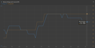
I am not convinced that the drain on the batteries is a purely resistive load, which a battery bank resistance would be. What I am seeing in the graph... before the sun came out is a steady current, but a varying voltage. The voltage drop over time was not a straight line. In fact it had a periodic switching with a period of approximately 26 minutes. There is a timer in the circuit somewhere that is doing something every 26 minutes. I suspect the CCs are sampling the PVs and the batteries and in that process, it causes a ringing in the voltage. CCs trying to take a voltage reading could cause the .01v fluctuation seen every 26 minutes. After the ringing, the voltage is back immediately. Furthermore, a steady minus current of 300 mils would cause the voltage to decrease over time.

I think the drain we are seeing is from the charge controllers themselves. They require power from the battery bank. At 300milliamps over the 6.5hrs, we get 1.95Ah or energy used. The total voltage drop over time was just 160 millivolts. pretty much insignificant. The way to test that would be to disconnect the PVs and CCs late this afternoon and let it graph another 6.5 hours.

Any thoughts?

Oh Yes, the link to the battery tester. https://www.amazon.com/gp/product/B000AMBOI0/

Oh yes, the data on the test of 8 batteries. Sorry, i wrote that on a scrap of wood that was handy at the site. When I tested the batteries before, I put a load on each with a multimeter attached and left the load (automotive headlight) on for about 30 seconds. Reading showed all the batteries about the same strength. I will record the new postings when the new battery tester arrives.
 
I am not convinced that the drain on the batteries is a purely resistive load, which a battery bank resistance would be.

Not sure what you're getting at here. A load is a load. It pulls a current. Battery voltage drops in response.

What I am seeing in the graph... before the sun came out is a steady current, but a varying voltage. The voltage drop over time was not a straight line. In fact it had a periodic switching with a period of approximately 26 minutes. There is a timer in the circuit somewhere that is doing something every 26 minutes. I suspect the CCs are sampling the PVs and the batteries and in that process, it causes a ringing in the voltage. CCs trying to take a voltage reading could cause the .01v fluctuation seen every 26 minutes. After the ringing, the voltage is back immediately. Furthermore, a steady minus current of 300 mils would cause the voltage to decrease over time.

I'm at a different location and do not have access to your VRM at the moment, but the above sounds plausible. I don't see any significance to the issue. The small load from the Cerbo, MPPT(s) and even the idle load of the inverter aren't a factor in this. All evidence continues to point to a system issue (batteries, connections, etc.).

I think the drain we are seeing is from the charge controllers themselves. They require power from the battery bank. At 300milliamps over the 6.5hrs, we get 1.95Ah or energy used. The total voltage drop over time was just 160 millivolts. pretty much insignificant. The way to test that would be to disconnect the PVs and CCs late this afternoon and let it graph another 6.5 hours.

Any thoughts?

Yep. You have troubleshooting to do to identify:

IMHO, one or more of the following:
Bad connections (loose, poor quality)
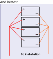
Bad battery configuration (not wired to share current per my sketch or the options listed by @chrisski ).
Battery imbalance (the two 12V in series forming a 24V are not the same voltage).
Batteries shot.


Oh Yes, the link to the battery tester. https://www.amazon.com/gp/product/B000AMBOI0/

Fan of that BT-100. I have one as well. Make sure you use it with a separately attached voltmeter and write down all your values:

Starting voltage
voltage immediately before terminating the test.

Run each battery 15 seconds and allow 1-2 minutes cooling between each one - forced air if you can.

Oh yes, the data on the test of 8 batteries. Sorry, i wrote that on a scrap of wood that was handy at the site. When I tested the batteries before, I put a load on each with a multimeter attached and left the load (automotive headlight) on for about 30 seconds. Reading showed all the batteries about the same strength. I will record the new postings when the new battery tester arrives.

Doubt an automotive headlight put enough load on it to give meaningful results.
 
11:30am PDT update with measurements and thoughts....

It is a mostly cloudy day. Chargers do what they can with what they have. It got really dark with the heavy clouds and the charge current on the system went to 300mils.

When outside, I checked the displays on each CC. The readings are as follows:

CC #1: 28.65v and .040a Charge Current on the display

CC #2 28.70v and .040a Charge Current on the display

CC #3 28.19v and 1.98a Charge Current on the display. This CC appears to still be in Absorb (1.98a is all it can make with no sun) while the other 2 are sitting in Float (0.040a)

Department of Redundancy Department below…

It appears that the CC#3 sees a lower voltage and is charging at Absorb. The other 2 are very close and sense that the voltage level is sufficent and put the charge rate at a Float charge current level of ~0.04a.

I guess I could go to the setup menus on the 3 CCs and see if there is a parament setting for Bulk, Absorb, and Float.

Battery bank read with a quality MM reads:

27.96v at the battery terminals, and between the 2 small bus bars, and at the + battery connection at each CC.

The sun not visible, and this #3 CC was the only one doing anything.
 
Not sure what you're getting at here. A load is a load. It pulls a current. Battery voltage drops in response.
It would appear that you are trying to find where the leak of 300mils is going. The inverter is not connected to the system and was not connected all night during the test.

I think the thing that I was trying to present was that even with the inverter disconnected from the system, there is still a current drain, and a periodic pulse. Either the 300mils is real which leads to the Ah drain over night, or, the shunt is not measuring current correctly and is reading 300mils low. Calibration time.

The power consumption of the CCs plus the Cerbo could be the drain that pulls the batteries down at night.

Time to tear the battery bank apart, measure each battery voltage, charge each battery with my NOCO GeniusPro50 charger, measure the "Charged Voltage", and then finally test each battery with the battery tester.

Battery connections were cleaned, reconnected, and torqued in November and there is not sign of corrosion.
 
11:30am PDT update with measurements and thoughts....

It is a mostly cloudy day. Chargers do what they can with what they have. It got really dark with the heavy clouds and the charge current on the system went to 300mils.

When outside, I checked the displays on each CC. The readings are as follows:

CC #1: 28.65v and .040a Charge Current on the display

CC #2 28.70v and .040a Charge Current on the display

CC #3 28.19v and 1.98a Charge Current on the display. This CC appears to still be in Absorb (1.98a is all it can make with no sun) while the other 2 are sitting in Float (0.040a)

The above strongly suggests all batteries are at true 100% soC.

Department of Redundancy Department below…

It appears that the CC#3 sees a lower voltage and is charging at Absorb. The other 2 are very close and sense that the voltage level is sufficent and put the charge rate at a Float charge current level of ~0.04a.

This isn't uncommon.

I guess I could go to the setup menus on the 3 CCs and see if there is a parament setting for Bulk, Absorb, and Float.

Battery bank read with a quality MM reads:

27.96v at the battery terminals, and between the 2 small bus bars, and at the + battery connection at each CC.

how does that compare to the shunt?

and what were the values for the individual 12V?

It would appear that you are trying to find where the leak of 300mils is going. The inverter is not connected to the system and was not connected all night during the test.

I think the thing that I was trying to present was that even with the inverter disconnected from the system, there is still a current drain, and a periodic pulse. Either the 300mils is real which leads to the Ah drain over night, or, the shunt is not measuring current correctly and is reading 300mils low. Calibration time.

The power consumption of the CCs plus the Cerbo could be the drain that pulls the batteries down at night.

Ah. Yeah. I just assumed that. It's pretty clear that all the listed loads only present a very small portion of the total capacity of the bank.
 
The above strongly suggests all batteries are at true 100% soC.


This isn't uncommon.


how does that compare to the shunt?

and what were the values for the individual 12V?


Ah. Yeah. I just assumed that. It's pretty clear that all the listed loads only present a very small portion of the total capacity of the bank.
After all the cables being disconnected for about an hour and a half and the batteries were fully charged when I disconnected them they're all sitting at 13.0 volts with the exception of two which are 13.1

The system is totally down now all the batteries are disconnected from each other and disconnected from the electronics. All the posts look clean but I'll clean them up and and I will rewire it according to the diagram that was given which is basically what I had two series and four parallel it's just that I did not have all of the cables the same length so I'll do that. It's more money to check out but I guess got to bite the bullet huh. So I'll let you know here when the system is back online might be a couple of days it will be nice weather tomorrow it didn't rain today and I ran the solar on two circuits today just to see what would happen with a little bit of sunshine thanks for all your help catch you next time

So you basically had 4P2S? Two groups of 4 in parallel wired in series?

The sketch I provided for 2S4P allows you to assess each battery individually as you can measure all 8 of them at any time. You could even individually load test them without breaking down the bank.

It is important that the battery interconnects be as consistent as possible. Altering the cable lengths will affect the way current flows through the batteries.

12V tester in yet?
Read again in my post above. 2s4p! This is a quote from that line.

"I will rewire it according to the diagram that was given which is basically what I had two series and four parallel "

4 parallel groups of 2 batteries in series. That is how they were wired today before I took the bank apart. Someone on here said I needed to take apart my bank and measure all the batteries and clean the posts. I did that last fall, and not change. So, doing it again, with new cables, all the same length. After this, at 75, I need to go back to work and earn a living. :)


When I get the tester I will let you know. Amazon says the tester arrives friday. We get deliveries out here between 5-7pm but they just say it will be delivered by 9pm!
 
So you basically had 4P2S? Two groups of 4 in parallel wired in series?

The sketch I provided for 2S4P allows you to assess each battery individually as you can measure all 8 of them at any time. You could even individually load test them without breaking down the bank.

It is important that the battery interconnects be as consistent as possible. Altering the cable lengths will affect the way current flows through the batteries.

12V tester in yet?
Thursday Morning update:

* One of the batteries read 11.7v this morning after sitting all night not connected to anything. THE CULPRIT!
* I put it on the charger (NOCO GeniusPro50) for 2 hr. The battery read 13.7. I will let it sit and check it again in a bit.
 
Wait, NOCO Pro 50?

The same NOCO Pro50 that lists for $900? Man I gotta do my hobbies better like you ?

Were you charging that single 100ah sealed battery at 50a, or are you able to lower the charge current? SLA batteries have a high current limit, I don’t think they like to charge close to .5c
 
Wait, NOCO Pro 50?

The same NOCO Pro50 that lists for $900? Man I gotta do my hobbies better like you ?

Were you charging that single 100ah sealed battery at 50a, or are you able to lower the charge current? SLA batteries have a high current limit, I don’t think they like to charge close to .5c
Sorry, if I were not living on SS and had a deep pocket of cash to spend, I might have money and time for hobbies. I think men should retire in their 20s when they have the money and strength to do hobbies, and then start working when they are about 30. Then, we could just work till be drop rather than wishin we were fishin but SS just doesn't leave extra for that.

Solar is not really my hobby. I love to do it and it is interesting but it is a necessity where we live. We are without grid power many times per year. Sometimes for more than a few week, but mostly only for a few days. The longest was about 3 weeks with 3ft of snow on the ground. I have a generator but it requires gasoline. When we have 2-4ft of snow and are home bound and the generator is out of gas, things are really rough. Our home is an all electric home. Heat, 680ft deep well, electric range, electric water heater. In the summer we have "Rolling Blackouts" when the grid power companies shut off the grid for hours to days when the temp is high and the humidity is low. They don't even want us to use generators because of fire danger and air quality.

We need electricity for medical stuff. Solar does not pencil out in Oregon. Not even close. No Sun 9 mos out of the year.

I need to keep the solar working and I run it to try to recover some of the money I put into it. I like the electronics since my degree was in electronics engineering. I was a design engineer at Tek for a few years and taught electronics, programming, and equipment repair and troubleshooting for Tek. Taught a couple of classes for Portland State. Was a Senior Software Development Engineer for Mentor Graphics for 10 year. Did IT work the rest of my employment days till I retired.

Actually, the NOCO is used to backfeed the battery bank when there isn't sun in the winter and the power is out. The NOCO runs off the generator along with the rest of the house. Then, at night when the generator is turned off, we have electricity from the bank of batteries to run lights and other needed stuff in the house. The batteries are not always charged by solar!

Solar is too expensive to be a hobby on SS. Have been without grid and gasoline in the dead of winter before and it is not fun. So, I use my education to help me create what we need. Never learned about solar cells in college. But then, that was over 50 years ago.!

Yeah, I know. Too much information. Oh, BTW, I bet your hobby, the 740GLE, cost more than my solar! :) Mmmmm!
 
Last edited:
EDIT: forgot the system was 24V.

Looks like the Noco has a 10A setting for smaller batteries. Definitely recommend that.

For 24V, https://www.donrowe.com/powermax-pm3-50-24lk-converter-charger-p/pm3-50-24lk.htm

50A @24V adjustable voltage for $228.
Yeah, the NOCO is a professional computerized charger that senses the type of battery, the voltage, and tailors the charging rate for the battery. 25a at 24v is the max. I don't think that it will harm my battery bank of 8 100Ah Deep Cycle RV batteries wired in 2s4p. The 3 charge controllers would burn up the batteries if that were the case. The charger needs to charge the battery bank completely during the time the generator runs in the daylight.

Oh, BTW, I replaced the marginal battery today and rewired the battery bank per the wiring diagram. Got it all up and running before the sun went down but there wasn't enough sun to test any thing. I will see tonight how the discharge graph compares with before. Rain all day tomorrow so there won't be much sun to test charging. But, there is a good chance that it will be better. I will have to replace the 2 wimpy busses when I recover from buying a new battery today. :)

I chose this design after viewing all of the suggestions!

1680239218515.png
 
Yeah, the NOCO is a professional computerized charger that senses the type of battery, the voltage, and tailors the charging rate for the battery.

Most of that is marketing. Noco is indeed a top brand and quality stuff, but they're horribly overpriced. I'd get better results with a $50 30V/10A power supply and/or one of the ~$200 adjustable power supplies/converters I mentioned. All that really matters is voltage and current, and no canned charger is going to be right for all batteries. A device that can be set to a specific voltage is what you want.

25a at 24v is the max. I don't think that it will harm my battery bank of 8 100Ah Deep Cycle RV batteries wired in 2s4p. The 3 charge controllers would burn up the batteries if that were the case. The charger needs to charge the battery bank completely during the time the generator runs in the daylight.

You want to charge at about 0.1C if possible. That's 40A in your case. 25A is okay, but it's not optimal.

Oh, BTW, I replaced the marginal battery today and rewired the battery bank per the wiring diagram. Got it all up and running before the sun went down but there wasn't enough sun to test any thing. I will see tonight how the discharge graph compares with before. Rain all day tomorrow so there won't be much sun to test charging. But, there is a good chance that it will be better. I will have to replace the 2 wimpy busses when I recover from buying a new battery today. :)

I chose this design after viewing all of the suggestions!

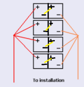
Did you do it more like this?

1680245617304.png


Four groups of two in series that are then wired in parallel?

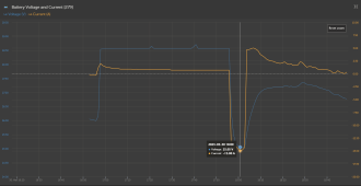
Your VRM is showing interesting results:

1680245893144.png

A 16A current change produced about 3.5V drop... That's

3.5/16 = 0.22Ω

This is still pretty horrible, BUT the data is dirty (comparing a voltage during a charge to a voltage during a discharge is pretty unreliable), AND it's dramatically better than it was. It's only 27X higher than my results, which is about a 5X improvement.

Hopefully when your BT-100 gets there Friday, your bank is wired in such a way that you can test each one individually without breaking the bank down.
 
Using that NOCO 50A for your full bank charging at 25A is fine.

Using that same charger of 50a on a single battery trying to restore it, will cause harm for that single battery, please make sure you use the 10a setting.
 
Back
Top