diy solar

diy solar

Settings for Victron SmartShunt 500/50mv

A 16A current change produced about 3.5V drop... That's

3.5/16 = 0.22Ω

This is still pretty horrible, BUT
No, the 1100 watt microwave was turned on for 3 minutes when there was NO SUN. :) Testing to see what a load would do to the bank. Also needed coffee to warm up a bit. There is a cold front coming in and snow is on the way again. That is why I wanted to get everything buttoned up so quickly.

The drop of 3.5v is a change in level rather than a level. I think that Ohm's Law might not work in this case. Maybe calculus! Somebody help me out with this since it has been a long time since I did calculus. I'm probably wrong......

Yep... that's what I was referencing:

This is still pretty horrible, BUT the data is dirty (comparing a voltage during a charge to a voltage during a discharge is pretty unreliable), AND it's dramatically better than it was. It's only 27X higher than my results, which is about a 5X improvement.

a 5X improvement in this case means the actual improvement is likely better.

Run a small load for about 5 minutes. Hit it with a larger load for a couple minutes and return to the small load. This makes for a pretty decent resistance check.
 
Using that NOCO 50A for your full bank charging at 25A is fine.

Using that same charger of 50a on a single battery trying to restore it, will cause harm for that single battery, please make sure you use the 10a setting.
I have even heard from a very knowledgeable person, on this forum, that has tested the use of a grid powered DC supply that has voltage and current characteristics that would emulate PV panels and also meet the input requirements of an MPPT Charge controller. The DC charge power supply would then feed the solar CC (in place of PV Panels). If the DC power supply has the optimum voltage and current output to cause the CC to charge at its best level (MPPT), the setup charges the battery bank with the optimum solar battery-bank parameters. It will therefore charge at a max level but not damage batteries because it is a charge controller made for charging battery banks. I rather like that idea of a gloomy day back-feed charger.

The guy's initials are WP. You may have heard of him. I trust him. You should too! :)
 
Did you do it more like this?

1680245617304.png


Four groups of two in series that are then wired in parallel?
Yes, 4 groups, of 2 in series, with the groups wired in parallel.

The 4 red cables in the drawing that come to an apex and then connect to the system are now 24", all equal in length. The orange are also 24". There still could be unequal charging, in that, current will find the path of least resistance. Only way to know how current is being routed would be to put a shunt on each leg. 4 new shunts are out of my pay grade!

Also, none of the cabling is connected to the lead posts of the batteries. All of the batteries are the same and have stainless steel lugs on the top next to the terminal posts. I used those.
 
I have even heard from a very knowledgeable person, on this forum, that has tested the use of a grid powered DC supply that has voltage and current characteristics that would emulate PV panels and also meet the input requirements of an MPPT Charge controller. The DC charge power supply would then feed the solar CC (in place of PV Panels). If the DC power supply has the optimum voltage and current output to cause the CC to charge at its best level (MPPT), the setup charges the battery bank with the optimum solar battery-bank parameters. It will therefore charge at a max level but not damage batteries because it is a charge controller made for charging battery banks. I rather like that idea of a gloomy day back-feed charger.

The guy's initials are WP. You may have heard of him. I trust him. You should too! :)
Not sure what you are trying to say with all these words. Any current source charging a battery should be matched to the battery specifications of max charge current, this is especially so for SLA batteries.

50a charger into a 12v SLA 100a battery may cause damage to that battery.

Each manufacture will specify the max current that is safe for the battery.

Just trying to save some expenses if you find yourself toasting battery after battery due to operator error.
 
I have even heard from a very knowledgeable person, on this forum, that has tested the use of a grid powered DC supply that has voltage and current characteristics that would emulate PV panels and also meet the input requirements of an MPPT Charge controller. The DC charge power supply would then feed the solar CC (in place of PV Panels). If the DC power supply has the optimum voltage and current output to cause the CC to charge at its best level (MPPT), the setup charges the battery bank with the optimum solar battery-bank parameters. It will therefore charge at a max level but not damage batteries because it is a charge controller made for charging battery banks. I rather like that idea of a gloomy day back-feed charger.

If you're saying you can use a power supply as input to an MPPT, this has been well documented - even by the founder of Midnite Solar.


The supply voltage must be acceptable to the MPPT, i.e., it must typically be X Volts above the battery voltage. For a Victron, the starting voltage must be +5V above battery voltage, and once started, +2 above battery voltage.

The guy's initials are WP. You may have heard of him. I trust him. You should too! :)

No need to be coy.

Yes, 4 groups, of 2 in series, with the groups wired in parallel.

Good.

The 4 red cables in the drawing that come to an apex and then connect to the system are now 24", all equal in length. The orange are also 24". There still could be unequal charging, in that, current will find the path of least resistance.

Good.

Only way to know how current is being routed would be to put a shunt on each leg. 4 new shunts are out of my pay grade!

Nope. You could also get a clamp DC ammeter and simply test each string under heavy loads and charges to confirm that they are sharing current roughly equally.

Also, none of the cabling is connected to the lead posts of the batteries. All of the batteries are the same and have stainless steel lugs on the top next to the terminal posts. I used those.

That's fine and likely gives you potential for more consistent connections.
 
Not sure what you are trying to say with all these words.
Sorry about all the words. Short and sweet:

Your Solar charge controller driven by PV panels will charge your batteries when the sun is out and the batteries need charging. That charge controller is specifically made for your battery bank.

Photon Sorcerer​

Your Solar charge controller(s) will NOT overcharge or improperly charge your battery bank.

Will Prowse, the owner of this DIY Forum board and owner of the YouTube Channel YouTube.com/@WillProwse did a video about using a high quality DC regulated power supply attached at the input to a charge controller instead of depending on PV. Somewhat like SHORE POWER. The DC power supply was connected to SHORE POWER, the grid. The output of the DC Power supply was connected to the PV input of a charge controller, and not PV Panels. The CC was the device charging the batteries and the DC power supply was only taking the place of PV Power.

Check out Will's site at the link shown above. His video can describe what he did and how it works much better than my words.

No sun here today. Wind is blowing and snow is predicted for this evening. Storm warnings in effect for the NW Oregon Coast Range.
I’m not sure how any of this applies to my advice about using too high of a current to single battery.
 
I’m not sure how any of this applies to my advice about using too high of a current to single battery.
Your advice has been taken to heart and followed. You can see that in the was that the rack is now wired. Thank you for all you have contributed to my effort to make this off grid work will.

Only thing I can say is that the engineers of the the NOCO battery charger are most likely smarter engineers than I ever was. I read the manual and trust their design to do what they say. They say it is computerized and analyzes the battery, then charges accordingly to its needs. I have to believe that.

Sorry, I am so frustrating for you. I am going to bow out of this one.

Again, thanks for your help.

Ken

I'll chime in. It is NOT smart enough to know if it's sending too much current to the battery. That's in evidence by the fact that it says there's a 10A mode.

Per the manual: https://no.co/media/nocodownloads/format/g/e/geniuspro50_user_guide_10.12.2022a.pdf

13.) 10A Mode Button Push to activate Reduced Charge Current Mode.

If you are using the Noco to charge one of your 12V batteries, you need to press that button. The charger is not smart enough to know that it's going to damage your battery by sending it 50A.

I'm going to repeat myself. I would get better results in every situation with a programmable power supply or charger than the Noco could ever produce in terms of PROPER charging of a specific battery.

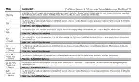
The Noco uses generic values that apply to certain types of batteries:
1680321512516.png


For example, under 12V for WET, it charges to 14.5V. If you put this charger on a Rolls-Surrette or Trojan 12V battery, you would UNDER-charge them as they are 15.0V and 14.82V, respectively.

All batteries have very specific "fully charged" criteria according to the manufacturer. There's no way the Noco can know these values, so it's just going to use something that's typical for that class of battery.

The Noco is a fine charger with important features, namely the "force," "supply," and "repair" modes, as they go above and beyond a standard charger; however, you can't fall for the marketing. Do not place blind faith in it. It doesn't know about specific batteries because it can't due to the hundreds (thousands?) of different battery brands and types that all may be slightly different.

Here's a little something that should shake your faith in them:

1680322184349.png

1680322172567.png

They only give you a caution that is vague.

What they should have said is:

These modes are ONLY for WET lead acid batteries. Repair mode on Sealed, AGM or GEL batteries will damage them.

So, before you wonder if it could help, NEVER use the repair mode on your batteries unless you want to damage them.
 
Back
Top