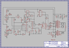
"But what is D2 ?"
Won't I need a Blocking Diode? (To stop the battery discharging through the pv's at night).
D2 is in the battery circuit where it is now.
If you want to add a series diode into the solar circuit, it has to be connected to U3 not U10.
And I suggest you remove Vcc net from U3 as well. The Vcc net does not appear to be used for anything else, so better remove it from U3.
D2 can be fitted external to the board, which is what I did.
I can't believe how I missed all this the first check either.
I cannot post Gerbers here on the Forum, and that is all I have to show what goes where.
My camera and document scanner are both broken, so cannot even post a sketch of how I ran my thick tracks.
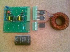
First lay out the 10 way terminal block, and the six way terminal block near the right hand edge of the board as I did. (also exactly as shown on the schematic).
Then place C11 at the top of the board with the +ve side pointing up.
Then place C12 and C13 side by side at the bottom of the board, with the +ve sides also pointing up.
The first picture shows the placement of these main components.
Run a thick horizontal track from BAT+ (pin 9) across to C11 + and also link (pin 9) to choke (pin 8)
Run a thick vertical track between the terminal blocks and the edge of the board, linking SOL+ (pin 10) The drain of the upper mosfet (pin 6) the drain of the lower mosfet (pin 2) of the ten way block, and (pin 4) of the six way block.
Run a thick horizontal track from (pin 4) of the six way block horizontally to the +ve sides of C12 and C13.
Run a thick vertical track to the left hand side of the terminal blocks between the source of the upper mosfet (pin5) to the source of the lower mosfet (pin1) of the ten way block. From there, pin (1) of the ten way block, drop a vertical track straight down to choke (pin 6) of the six way block, on down onto (pin 5) of the six way block.
Run thick ground tracks connecting all the capacitor negatives to pins 1 and 2 and 3 of the six way block.
You can first follow all this through from the schematic.
Duplicate all of those thick tracks on BOTH sides of the board, make them as wide as possible, and specify two ounce copper.
Once that is done, all the other tracks can be placed.
I very strongly recommend you follow my thick track layout, making any changes to the physical layout will complicate things hugely.