diy solar

diy solar

Slim configuration & flexible busbars (280AH)

Joined
Jul 6, 2020
Messages
105
Hey crew,
Currently have the standard configuration of 4s 280ah & I want to change it to a "slim" configuration.
config new.png
This install is four my four wheel drive and in the current configuration it takes too much space up unnecessarily.

Now, the trade off for this configuration is the mechanical integrity of the battery. So I believe flexible BUSBARS would be a much safer option. Would this braid be sufficient? and I'll just use tinned copper pipe for the lugs, pressed on the braid. https://tinyurl.com/y2alnuxq.

To give strength to the longest side of the battery to provide adequate compression for optimum battery health, I will 3D print INDIVIDUAL cell casings, which will slide into a plywood box.

Are there any flaws in this, or advice?
Thanks in advance!
 
I think it should work. I don't think you are supposed to be rough with the 280ah cells.
I guess your 3D printed holders should keep them from bouncing around too much.
You'll probably hear from others with more experience than me.
 
8.3mm^3 is the equivalent of about 8 awg. Fine as long as you don't pull more than about 60A, but pure shite compared to the solid bus bars.
 
I don't do hardcore four wheel driving, but am in Australia and the road corrugations would probably be the harshest thing on the battery. Would be nothing of the larger sudden movements in a marine install.

Is the issue withe movement in batteries just the wear on the terminal and forces coming from there? or is there something inside the battery affecting it. The battery box is on rubber to dampen the vibrations a bit.

Crazy they advertise that braid at 290A. My bad, I overlooked the cross sectional diameter and just looked at the rating. What about if I layered it to increase current?

Other option- I cut this one up https://au.rs-online.com/web/p/braided-wire/0489153/
Would you heat shrink the braid to protect it a bit?

What are the issues with using an overrated braid as a BUSBAR vs a solid?

Cheers
 
The problem comes if the cells move independantly of each other at all or independantly of the wires connecting them to the system.

Have a look at your vehicle battery, it will be held very securely on a bracket attached directly to the vehicle body, no rubber mat etc. This is because its the best way to hold a battery to prevent any problems, that mount have been engineered by automotive design engineers. Copying it is your best option

What are the issues with using an overrated braid as a BUSBAR vs a solid?

As long as it has the same cross sectional volume as the recommended wire for your current and the connection is good in your home made terminations then I really like the idea of a flexible busbar. Less chance of stress on the terminals
 
Since you are 3D printing holders, it seems like you should be able to lock the cells in place and use the solid buss bars. 2 thin solid copper buss bars might give you a little flex.
 
There is nothing wrong with using braided wire unless you are an Electrical Engineer who has learned too much. As for the rest of us it just works and not knowing any better makes it even more simple. To explain what I said according to EE types it wont work according to hard knocks it works fine. maybe some day in 10 years it will break until then it will be fine.
 
Crazy they advertise that braid at 290A. My bad, I overlooked the cross sectional diameter and just looked at the rating. What about if I layered it to increase current?

No they don't. Its part number ends in a ".290A"

clearly says on the page it's rated for 90A. When a datasheet is provided, you really need to read it:

1598504442202.png

It can certainly handle 90A, but I don't want my bus bars causing burns if something touches them.
 
Last edited:
You can certainly use a Good Quality braided bus or make your own up from Copper or Aluminium and you'd be good to go in that respect. The Ble Cells do NOT like abuse, it is actually very easy to puncture them you "MUST" protect the cells from chafing, rubbing, impacts and any possible contact with power wires on the casing. Harsh jarring or bashing can also result in internal damage.

You have to protect the sides of the cells as well as the top & bottom. Some form of cushioning / padding underneath would not hurt (water proof).
 
This guy sells braided buss bars. Scroll down on here; http://store.evtv.me/products.php?cat=7&pg=2
If you do use copper pipe compressed onto braided copper strap, Use solder and tin plate the inside of the pipe before compressing on the strap. Make it real tight as with a hydraulic press.
 
Flat uninsulated bus bars, be them braided or solid, will have a higher current rating than normal cable/wire. This is due to the lack of insulation to melt, and better heat dissipation than round profiles. Just because they can safely carry the current, doesn't mean the voltage drop is acceptable. So make sure you aren't creating an issue with the extra voltage drop when loaded.

There is absolutely nothing wrong with using cable, or flat braided ribbon to make short jumpers to connect the cells. Just use quality thick wall terminals with a solid crimp. Solder can work as well, but with short cable runs, wicking can pose flexibility issues.

In some situations make in short insulated cable instead of a bus bar is preferred. They are already insulated for most of their length, are more flexible, and can be made using existing cable and terminals from the project/system. They are more tolerant of fabrication precision, where a bus bar needs to be precisely drilled, a cable can very +/- 4mm without issue.
 
Thanks for the reply all.

So if I am tinning before the pressing of copper ends/lugs. Shall I tin the outside of them after pressing also?
I was initially thinking of using some 2AWG cable, but I would probably have to fashion a lug in a way that it offsets the thickness of the wire/insulation and doesnt press on the cell. Undoing all the effort of creating a flexible application.

I didn't consider "chafing" of the cells. Would a tire inner tube cut up suit the surround of a cell within the 3d printed case?

I might actually "double up" the first wire I posted, much cheaper and I will get more leftovers for future builds. 180A rating gives me at least 60A headroom on top of my 120A BMS. :) I will order the wire now and start designing these 3D printed cases and share photos! :)
 
I'm also going to adopt the SLIM configuration as shown in first post. But in my case it will be a 8S /24V configuration, hence I will have 2 rows of 4 cells. Advantage of this scheme is:

- Both (+) and (-) come at same end -> less main cable to use (in my case) as it will be optimal distance to inverter.
- Needs slightly longer jumpers (or differen busbar). But since I don't have good experience with the resulting contact resistance of busbars, I'm now using 25mm2 cable + lugs, and the issue is we need a certain minimum lenght to have some difficulty. Hence, the distance between poles raises from 7 cm of standard configuration to about 9cm of this SLIM config. That's why I see it as an advantage. :)

There is a non-slim approach with cells next to each other on the long edge, all cells having (+) and (-) facing same side, and with "Z" fashion jumpers of a sensible 11 cm. With this distance, it will be possible to use 35mm2 cable. It can be a goof approach to those that need main (+) and (-) on different sides of the pack.
 
Better than Braided busbars?

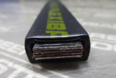
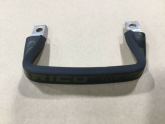
Eriflex Flexibar has insulated plastic on the outside and tinned copper on the inside. This comes from the factory on UL starters and drives of over 1000 amps. Normally installed between the starter and the motor.

Measure it up and cut to size. Drill a hole in it through the bars. Cut the plastic back to expose the conductor. No need to add wire connectors or shrink wrap on the ends. A slight bow from terminal to terminal will allow for expansion if needed.

There are different sizes and amperage up to 2000 amps, the link below is listed for 400 amps. The size in the link is Width: 0.79 Inches Height: 0.24 Inches Length: 78.74 Inches.

1601357276982.png1601357466901.png
 
Last edited:
2020-10-01_05h12_17.jpgI did mine in this configuration. Using 1" x 1/4 copper bar.
 
Back
Top