225A panel, 200A main, 120% rule allows 70A PV breaker. 80% loading allows 56A continuous, at 240V 13,440W.
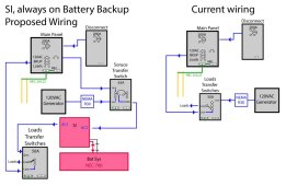
Fed by 70A breaker in main panel, 2x SI can work as UPS for downstream loads panel. Have a critical loads and PV aggregator panel for SB so always powered (also critical loads like alarm, communications), then a load-shed relay supplying important loads panel. Default that would be disconnected at 30% SoC.
Backfeeding an interlocked "generator" breaker of main panel, you can manually supply that as well. I have that on same 30% load shed, will move it to 80% SoC load shed relay eventually. Have to turn off 70A breaker feeding SI when SI feeds that panel.
Back in the Sunny boy 5000 ~ 8000US days, I think "backup" was by default off and it would not respond to RS-485 and frequency-shift power control. Have to get it running with PV and AC (frequency has to be within spec) before it will listed to an RS-485 master so you can configure it. While my SI was at 59 Hz it wouldn't connect, but with grid feeding at 60 Hz I could connect and configure it. Then it would switch to backup and work with wider frequency range. (Later models were shipped with backup mode enabled.)
Added PV wattage likely requires agreement with utility, and compliance to UL-1741-SA, which these older models don't support. Not that it matters behind SI, because SI will disconnect from grid at UL-1741 frequency limits. (Maybe a newer product would remain connected and let SB support grid at wider limits.) If only you had a way to export-limit at your agreement, added wattage would likely go unobserved. I don't know how to do export-limit with these inverters. Their production limit could be set over RS-485. I think dynamic adjustment for zero or limited export is supported on later models with SpeedWire. With your added PV wattage, whether PG&E notices or not depends on your loads, and what their programmers code into meter reading software.
If both SB had RS-485 then both would switch to backup mode and do frequency shift.
If both were set to off-grid mode, they would do their thing behind SI, and SI would disconnect from grid when grid was out of spec.
SMA America has given some recommendations about doing that for certain systems but I have misgivings - I think the "backup" rather than "off-grid" settings were planned by SMA Germany engineers to keep the system safe even in the event of faults (like stuck relays.)
Commands to SI probably would let it feed battery to loads or grid. Voltage, as you say, or grid current limit.
60A breaker feeding SI - 80% of rating would mean 48A continuous is max recommended. More than that and a thermal-magnetic breaker might nuisance trip. Consider 70A (although for one of AC1, AC2 manual says 56A breaker max?) Consider magnetic-hydraulic. Midnight/CBI 60A is guaranteed not to trip up to 63A (+5%), guaranteed to trip eventually at +30% or higher. Carlingtech the trip curve is +0% and +25%.
Is it still last year for 30% tax credit, or did that get extended for a decade?
I installed my system beginning around 2003, cost $8/W with rebate $4/W and utility rates were lower. That may have taken 15 to 20 years to break even. The SI addition is pure cost, but it was nice working in the home office with A/C going during power failures. I figure the home made cappuccinos cost me $1000 apiece.
Here's the SI-LS100-48 load-shedding contactor.
Maybe you can find a domestic source, and other parts could also work, but this one has an especially good economizer - high current relay pulls in, low current relay switched in series to hold.
System manager for all types of energy generators.

www.windandsun.co.uk
SolArk has more features/functionality, and responsive support. Time will tell if quality and durability is there. People compare to similar products from same manufacturer at a fraction the cost, which may have cheaper alternate components. SMA costs a lot because it is an expensive product, both how much it contains and source of components. What's lacking in these older models is newer features, but if we can roll our own with comms, that is OK. Latest firmware could break some things - Midnight has an interface for their Classic SCC, and said update broke that.


") If it isn't likely to have faults and we get similar protection then it comes down to cost savings ... and every time we can save money and do something safely and to spec we go for it :D
If it isn't likely to have faults and we get similar protection then it comes down to cost savings ... and every time we can save money and do something safely and to spec we go for it :D