diy solar

diy solar

Solar panels connected, battery bank disconnected

PhotonSailor

New Member
Joined
Jul 13, 2020
Messages
25
Hello All,

Am wondering if the following situation can this damage my equipment?

Am using Will Prowse blueprint - 400 Watt Solar Package w/ Alternator Charging
See

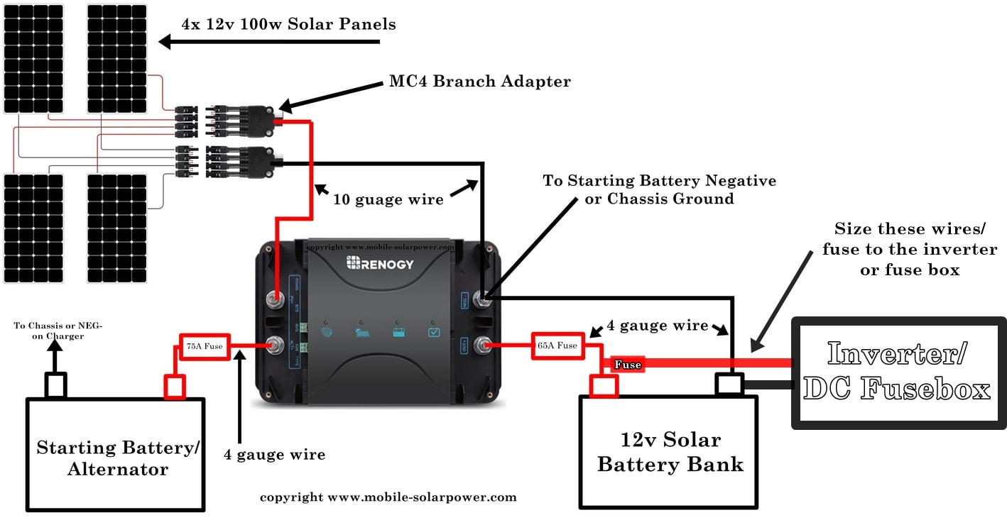
I have 3 circuit breakers with an ON/OFF switch.

* 250 Amp circuit breaker - Between the battery bank, inverter, DC fusebox and 70 Amp CB.
* 70 Amp circuit breaker - Between the 250 CB and the charge controller.
* 80 Amp circuit breaker - Between the charge controller and the positive terminal of my starter battery.

See

Now here is the situation.

I am outside with my vechile, there are Sun Power solar panels on the roof of vehicle and the sun is shining brightly.

Before I do any work on the system, I throw the ON/OFF switches on all circuit breakers to the OFF position.

But the solar panels are directly connected to the charge controller and the battery bank is not connected as I threw the switch on the 250 circuit breaker to the OFF position.

So the panels are collecting and sending electrical energy to the charge controller but the charge controller has nowhere to store the energy, battery bank disconnected due to circuit breaker in OFF position.

So, can this damage my system?

Should I place a circuit breaker (or something else) with an ON/OFF switch between the the solar panels and the charge controller?

Thank you for any assistance!
 
Should I place a circuit breaker (or something else) with an ON/OFF switch between the the solar panels and the charge controller?

Yes. Be sure to turn this breaker OFF before you turn the other breakers OFF.

The new breaker needs to be sized to handle the volts and amps that the panels can generate.
 
I'd be interested in seeing what the charge controller owners manual says about the voltage going into the SCC with no battery attached. If it's not in the manual, perhaps the tech guys will be responsive to E-mails.

I agree it's a good idea to add a circuit breaker between the SCC and panels and I have that between my charge controller and panels, but I hooked that up because I have panels in parallel, but I'm not sure I needed to do add this breaker because there is only two sets in parallel and there's plenty of builds out there with junction cables unfused. Also the my maximum series fuse rating is 15 amps, and my two parallel banks of panels added up does not exceed that amperage.

I have the CB between to SCC and panels that you asked about, the battery fusing you have, but I do not have the CB between the SCC and Battery fuse. This is a fifth wheel, not an RV with a alternator, so I don't have the fuse between the SCC and positive terminal of the starter battery.

I have considered adding more breakers, but each time I add a breaker, there's a chance for voltage loss. I plan on adding ground panels and I will add a breaker between the SCC and panels, but I'm not sure its necessary.
 
Most (all?) charge controller manuals tell you to turn on the charge controller to the battery first, then the solar panels. Victron (and I'm sure others) do come right out and say you will damage the charge controller if you send solar to it without the battery connected. A breaker is the easiest way to prevent this damage.
 
Most (all?) charge controller manuals tell you to turn on the charge controller to the battery first, then the solar panels. Victron (and I'm sure others) do come right out and say you will damage the charge controller if you send solar to it without the battery connected. A breaker is the easiest way to prevent this damage.
What damage?
Did you read this?
 
When the manufacturer tells me to my face that they know it will damage it, they have seen it damage it, I'm going to believe them.
 
I'd be interested in seeing what the charge controller owners manual says about the voltage going into the SCC with no battery attached. If it's not in the manual, perhaps the tech guys will be responsive to E-mails.

I agree it's a good idea to add a circuit breaker between the SCC and panels and I have that between my charge controller and panels, but I hooked that up because I have panels in parallel, but I'm not sure I needed to do add this breaker because there is only two sets in parallel and there's plenty of builds out there with junction cables unfused. Also the my maximum series fuse rating is 15 amps, and my two parallel banks of panels added up does not exceed that amperage.

I have the CB between to SCC and panels that you asked about, the battery fusing you have, but I do not have the CB between the SCC and Battery fuse. This is a fifth wheel, not an RV with a alternator, so I don't have the fuse between the SCC and positive terminal of the starter battery.

I have considered adding more breakers, but each time I add a breaker, there's a chance for voltage loss. I plan on adding ground panels and I will add a breaker between the SCC and panels, but I'm not sure its necessary.
Yep, Renogy DCC50S User Manual - Page 3 - "NEVER connect the solar panel to the charger without a service battery connection, The batteries must be connected first."
 
When the manufacturer tells me to my face that they know it will damage it, they have seen it damage it, I'm going to believe them.
I can understand your caution but did you read this from that thread?
Justin is a Victron dealer.

Can confirm that they don't actually care, and in fact require a fuse or breaker between the SCC and the battery. Technically the wording is in there because of a conceptual problem on paper that they wanted to make sure would never happen, but this was written before the days of LFP and BMS systems and all that. Their own systems now will shut off the battery when necessary, which would obviously create the very problem that they're trying to -theoretically- avoid.

I too have tried really hard to make a Victron SCC fail in this way, under various conditions including the full-bore-charging sudden disconnection event that the wording was theoretically written to avoid, and I have never managed to cause a problem by doing this.

The official word from Matthijs on this is that no one has ever heard of this condition actually causing a problem, it's just that an engineer back when his dad was originally developing these decided to include the language to cover for a theoretical problem that has never, in anyone's experience, actually occurred. With that in mind, they've been going through and slowly updating manuals accordingly... there definitely used to be some stronger language in the manuals that's now being removed (can't guarantee it's out of all the manuals yet) with only the language about connecting the battery first being left in - and that's just so the units can recognize and set the system voltage.
 
Last edited:
Yes. Be sure to turn this breaker OFF before you turn the other breakers OFF.

The new breaker needs to be sized to handle the volts and amps that the panels can generate.
Thank you!

Note;
The Renogy specs state;
  • Maximum Charging Current : 50A (25A Alternator / 25A PV)
  • Maxium Solar Input Voltage of 25V
If the maximum charging current that the Renogy DCC50S can handle is 25 Amps would that not be the determining factor, not the panels?

Also
I did a quick scan of circuit breakers on Amazon and so far I am nor seeing a 25 amp circuit breaker, only 20, 30, 40 and so on.

Since I couldn't believe that the maximum solar input is only 25 volts, I had to verify that. Yep, that's correct. My panels will be providing ~80 volts so that solar charge controller would have never come close to working for me. Even if I put my panels in parallel instead of series it wouldn't work. Since the PV side can only charge to 25 amps, maybe that's why the solar input is so low.

I would make doubly sure than your panels fit with that controller. If your battery bank is very large, you might want to reconsider that controller.

With regard to the panel disconnect issue, every RV trailer I looked at that has solar panels on the roof, has the connection to the controller active. However, these are PWM controllers, not MPPT. I'm not taking any chances with my system. Input to the solar charge controller goes off before I turn everything else in the system off. I put in a double pole breaker just for this situation. Your breaker should be slightly larger than what your panels can produce. I used a 40 amp breaker. 20 wasn't enough and the brand I used didn't have a 30 amp.
 
Most (all?) charge controller manuals tell you to turn on the charge controller to the battery first, then the solar panels. Victron (and I'm sure others) do come right out and say you will damage the charge controller if you send solar to it without the battery connected. A breaker is the easiest way to prevent this damage.
Hello Solar Queen, Enjoy your videos!

The Renogy DCC50S specs state;
  • Maximum Charging Current : 50A (25A Alternator / 25A PV)
  • Maxium Solar Input Voltage of 25V
Question
If the maximum charging current that the Renogy DCC50S can handle is 25 Amps would that not be the determining factor, not the panels?

Regarding panels, I have 5 SunPower Flexible panels, parallel-connected;

3 - 50 watt panels, each with;
  • Nominal Power (Pnom) 50 W
  • Rated Voltage (Vmpp) 17.7 V
  • Rated Current (Impp) 2.8 A
  • Open-circuit voltage (Voc) 21.5 V
  • Short-curcuit current (Isc) 3.1 A
2 - 110 watt panels, each with
  • Nominal Power (Pnom) 110 W
  • Rated Voltage (Vmpp) 18.8 V
  • Rated Current (Impp) 5.9 A
  • Open-circuit voltage (Voc) 22.8 V
  • Short-curcuit current (Isc) 6.3 A
Question
As they are connected in parallel the amperage is 2.8 + 2.8 + 2.8 + 5.9 + 5.9 = 20.2.
What size circuit breaker would you say is appropriate to put between the panels and the charge controller?

Also, a little confusion regarding which numbers to use from the specs, there are two different numbers for both voltages and amperage.

If you could shed light on this - it would make my day (and I'll grant you 3 wishes!)
 
Voc and Isc are the volts and amps you'll see when nothing is connected, open or short circuit. When measuring Voc, there is no current flow, so 0A. When measuring Isc, the panel is shorted, so there is no voltage differential, so volts are 0V. The highest numbers you'll see when actually connected and working are Vmp and Imp, volts and amps at max power. Those are the 2 numbers used to determine the watts of the panel. For example, 18.8Vmp x 5.9Imp = 110W.

Per National Electric Code, the breaker should be the sum of the Isc x 1.56, which is 34.1A, round up to 40A. Wires should be sized accordingly. That being said, this is for a trailer that doesn't need to follow NEC. I'd personally probably use a 30A breaker to avoid nuisance tripping.
 
I can understand your caution but did you read this from that thread?
Justin is a Victron dealer.
I didn't see that. Maybe it is just one of those things that they always tell you so often it becomes true. But, as most of my design work is for systems that require following NEC, it still requires a disconnect between the panels and the charge controller. Easiest solution for that is to just use a breaker. I just really like the ability to turn off the panels if needed.
 
Voc and Isc are the volts and amps you'll see when nothing is connected, open or short circuit. When measuring Voc, there is no current flow, so 0A. When measuring Isc, the panel is shorted, so there is no voltage differential, so volts are 0V. The highest numbers you'll see when actually connected and working are Vmp and Imp, volts and amps at max power. Those are the 2 numbers used to determine the watts of the panel. For example, 18.8Vmp x 5.9Imp = 110W.

Per National Electric Code, the breaker should be the sum of the Isc x 1.56, which is 34.1A, round up to 40A. Wires should be sized accordingly. That being said, this is for a trailer that doesn't need to follow NEC. I'd personally probably use a 30A breaker to avoid nuisance tripping.

Did you mean to go to a 50 amp breaker instead of a 30 amp? If not, can you explain that? I thought that you would reduce nuisance tripping by increasing the amp rating.
 
I didn't see that. Maybe it is just one of those things that they always tell you so often it becomes true. But, as most of my design work is for systems that require following NEC, it still requires a disconnect between the panels and the charge controller. Easiest solution for that is to just use a breaker. I just really like the ability to turn off the panels if needed.
Sorry to hijack the thread but even with a breaker between the panels and SCC the battery can still get disconnected if say the BMS shuts off or other reasons.
If that killed your Victron then there would lots of unhappy users.
 
Did you mean to go to a 50 amp breaker instead of a 30 amp? If not, can you explain that? I thought that you would reduce nuisance tripping by increasing the amp rating.
Sorry, I wasn't clear (I needed a nap). I was just saying in this case I'd probably round down to 30A instead of rounding up to 40A. I shouldn't have said anything about nuisance tripping, I was thinking people were proposing lower than 30A, but it just confused things.
 
Voc and Isc are the volts and amps you'll see when nothing is connected, open or short circuit. When measuring Voc, there is no current flow, so 0A. When measuring Isc, the panel is shorted, so there is no voltage differential, so volts are 0V. The highest numbers you'll see when actually connected and working are Vmp and Imp, volts and amps at max power. Those are the 2 numbers used to determine the watts of the panel. For example, 18.8Vmp x 5.9Imp = 110W.

Per National Electric Code, the breaker should be the sum of the Isc x 1.56, which is 34.1A, round up to 40A. Wires should be sized accordingly. That being said, this is for a trailer that doesn't need to follow NEC. I'd personally probably use a 30A breaker to avoid nuisance tripping.
Thank you for that!

There is still one little detail that is bugging me about breaker size.

I am new to this and to my way of thinking,

If the Renogy is rated for 25 Amps and if I put a 30 Amp CB as suggested between it and the solar panels, to me that seems like I am allowing more amps to get to the Renogy DCC50S could handle, exceeding its capacity and damage it.

It would seem that a 25 amp fuse would be what's needed.

Am I wrong?
 
The solar panels must be sized to not exceed the expected input of the solar charge controller. The breaker is there for a catastrophic electrical event, but mainly it's there so you can shut down the circuit between the solar panel and the solar charge controller.

For most solar charge controllers, it's the max input volts that you can't exceed. I don't know how many amps input your solar charge controller can handle. The 25 amp rating is on the output side, not the input side. So you would size the breakers to be slightly above what your solar panels can ever (normally) produce.

For MBR, the BMS is much more likely to cut off charging, than it is to cut off discharging. I would suggest that in most cases, if your BMS is cutting off discharge, then the solar charge controller probably isn't doing anything anyhow so there wouldn't be any harm.
 
Solar panels - on last /off first ... it is in the manual!

If your CC is a 12v/24v model you will have to reset everything in that order anyway.
Your CC may survive but what about everything else connected in the interim?
 
Yep, Renogy DCC50S User Manual - Page 3 - "NEVER connect the solar panel to the charger without a service battery connection, The batteries must be connected first."

In the instructions for my AIMS controller, they instruct to reverse the steps to turn system ON when turning OFF. That would imply following order to turn off:
  • Turn all AC and DC Loads OFF on the AC and DC panels ß--IMPORTANT
  • Turn the inverter OFF
  • Turn the Blue Sea inverter disconnect switch OFF (my system)
  • Turn the Blue Sea solar disconnect switch OFF (my system)
  • Turn the Blue Sea Solar Charge Controller to battery disconnect switch OFF (my system)
  • Confirm all devices are off and the state of the lifepo4 Battery BMS operation is AT REST
 
Last edited:
Back
Top