diy solar

diy solar

Solar panels won’t work in series?

Thorium

New Member
Joined
Apr 8, 2021
Messages
69
Newbie so probably something obvious I’m missing…

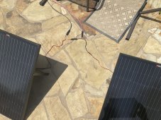
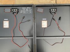
I have two panels I’m testing - rich solar 100w portable (https://richsolar.com/products/100-watt-portable-solar-panel-black)
connected to an MPP solar 101LV.

if I connect either panel alone, the MPP sees them.
if I connect both panels in parallel, the MPP sees them.

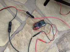
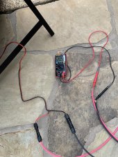
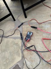
but if connect two (also tried 3) in series, the MPP doesn’t show anything connected.

All else remains equal, so that should mean all the wiring is fine right? What am I missing?
 
Checking the voltage at the PV wire coming back to the MPP solar unit, when the two panels are connected in series as shown in the photo, it has very low voltage like the two panels are canceling each other out.

But if you look at my photo, aren’t I connecting it in series properly? Positive to negative between the two panels connected, red goes back to positive PV on MPP solar, black to negative.

I did chop of the SAE connectors at the end of the panels wires and replaced with MC4, did I do something wrong there? The wires coming out the back of the panels and their connections to panels are as they came from factory.

each panel measured individually show the correct ~20v coming back thru the red and black PV wires.
 

Attachments

  • B4032953-C054-4556-835A-A1B0BE2C12E3.jpeg
    B4032953-C054-4556-835A-A1B0BE2C12E3.jpeg
    341.9 KB · Views: 29
Thanks for the input.

When either of the two panels is connected alone, and all else is equal — I measure the voltage at the end of the red & black PV wire going back into my house, and I get ~20V for both panels, each tested solo.

The same connectors, same PV wire, measuring voltage at same place, only difference is one panel at a time.

Doing those two tests (each panel solo) ends up testing all the exact same connectors, wiring, voltage measured in same place as I use for then connecting the same two panels in series.

The same stuff is then reconfigured into the two panel in series configuration, but then voltage measurement jumps around between 2-10 volts Instead of creating the 40 volts one would expect.

dont those tests eliminate faulty connectors/wiring?
 
Forgot to add, I also tried connecting same two panels in parallel. So that adds a 2-to-1 MC4 branch connector into the mix, but otherwise uses all the same stuff.

The parallel connection also worked fine and gave me the double amps expected.

I’ve sent Rich Solar a support email as well, is it possible these panels have some weird configuration? They are the special “portable” panels that come with built in stand and come standard with SAE connector For use on commercial solar generators.
 
Here’s a picture of these solar panels junction box in case somebody notices anything unique about them
 

Attachments

  • C790A510-C216-4920-96E3-EB06B8E05F11.jpeg
    C790A510-C216-4920-96E3-EB06B8E05F11.jpeg
    287.2 KB · Views: 32
MPP solar 101LV
I can't seem to find any information about your "MPP solar 101LV" SCC online. What is the maximum input voltage?

Are you measuring the output of the series connected panels with the SCC, or a multimeter? A multimeter measurement straight from the panels would help with troubleshooting.
 
I agree a multimeter and the panels in series is the best test for voltage.

Perhaps this MPP is actually a PWM and has a built in safety feature to avoid overvoltage.

What I’ve noticed with PWM controllers:

-When charging 12 volt batteries, they need 12 volt panels. I know some of you are furious because there’s no such thing as a 12 volt panel, but input voltage is limited to around 16-20 volts.

-When charging 24 volt batteries, they need 24 volt panels. I know some of you are furious because there’s no such thing as a 24 volt panel, but input voltage is limited to around 28-33 volts.

-PWMs don’t support putting panels in series for 12 volt batteries unless in series the total voltage is 16-20 volts. Very rarely is a panel you buy going to be less than that any any combination of two panels in series will exceed that limit.

-PWMs only support putting panels in series for 24 volt batteries unless in series the total voltage is about 28-33 volts. This only happens when you have two “12 volt panels” (avoid th cringing please.
 
Did you reverse the MP-4 connectors that you cut off? The one that looks like a male is actually female and vs versa. Double check the polarity of each wire coming off each panel to make sure you really have pos to neg.
 
When either of the two panels is connected alone, and all else is equal — I measure the voltage at the end of the red & black PV wire going back into my house, and I get ~20V for both panels, each tested solo.
disconnect the pink and black leads from the PIP 110 (Voc102v)Pwm PIP110 80voc) and measure the voltage at that end.
If not 40v then it must be the connectors , sometimes mixed brands of mc4s dont fit very well. If 40v it must be pip110lv.
You only have shown one connection box, the panels have been reversed?? Does your meter have a negative sign?

Take a reading of the panels in series with the leads reversed using the Y connector.
 
Show us the picture of your SCC and the spec.
The MPP Solar is LV1012-MS, manual

disconnect the pink and black leads from the PIP 110 (Voc102v)Pwm PIP110 80voc) and measure the voltage at that end.
If not 40v then it must be the connectors , sometimes mixed brands of mc4s dont fit very well. If 40v it must be pip110lv.
You only have shown one connection box, the panels have been reversed?? Does your meter have a negative sign?

Take a reading of the panels in series with the leads reversed using the Y connector.
all the measurements noted earlier were with a multimeter taken on the ends of the PV red/black wires inside the house,
i did get the multimeter to read the voltage in the 30s if I held the probes just right, and It did have a negative sign.
the other connection box looks identical, the connection boxes as are they came from the factory.

can you help me interpret what the negative sign means in the practical sense of what I need to do differently?
Even though I’m connecting based on the color of the wires coming out of the panels (which is how they came from factory) I’m reversing polarity somehow?
 
Here are photos with the ”entire system” (panel, connectors, PV wires) being read and each showing +20V…

then the third photo, Im using the exact same materials (same two panels, same connectors, now wired in series) and you can see the really low voltage reading (+3.7v) I get. In reality while the panels were connected in series the voltage fluctuated (which wasn’t an issue measuring the individual panels), but was in the 3-15v range mostly closer to 3 as I moved the probes around slightly, I don’t know if that is just changing light conditions or my movement of the probes that made it fluctuate (again not happening / not an issue when measuring individual panels the exact same way).

when the leads are connected to mpp solar with the panels in series the mpp never even recognizes that solar panels are attached.
 

Attachments

  • 14D3F65D-6D3C-42BD-85B8-F788C5E2B762.jpeg
    14D3F65D-6D3C-42BD-85B8-F788C5E2B762.jpeg
    259.7 KB · Views: 20
  • EDB9200E-7724-4349-90CA-CD31C192EBFD.jpeg
    EDB9200E-7724-4349-90CA-CD31C192EBFD.jpeg
    147.9 KB · Views: 20
  • BF98BEBA-EA38-48F7-ADD4-E3E4711D9820.jpeg
    BF98BEBA-EA38-48F7-ADD4-E3E4711D9820.jpeg
    134.7 KB · Views: 21
I have the same MPPT unit.
It looks to me one of the panel has reversed polarity so when you connect the two in series they cancel each other out.
Show us good clear pictures of the two panel side by side that also show the connectors on each wire.
 
Thank you for your help.
photo attached of the two panels, their connectors and open junction boxesl
 

Attachments

  • 763850DE-6C82-4740-9B37-2A6103A7FED2.jpeg
    763850DE-6C82-4740-9B37-2A6103A7FED2.jpeg
    99.3 KB · Views: 33
They look correct.
If you check the Voltage of the left panel, it shows 20VDC not -20VDC, correct?
Then when you connect the Positive (RED) wire MC4 of the left panel to the Negative (Black) wire MC4 of the right panel and then you check the DCV on the not connected MC4 connector of each panel, you are not getting about 40VDC but - 3 something Volt?
 
They both show 20vdc (positive) as expected when tested from the junction box (eg red probe to where red wire comes into junction box)… I checked each at the junction boxes earlier today.

Sun haa just gone down here in Texas so I’ll have to resume tests tomorrow.

sincerely appreciate the help, this is really puzzling me.
 
I’ll do that Tomorrow.

keep in mind that when I connect either of these panels solo, using all the same pieces (same panels, connectors, pv wire) and connect the PV to MPP Solar, they work fine.

I can also connect both in parallel with a branch connector thrown into the mix and the MPP solar sees that just fine too.

im trying to figure out why all that would work and only series causes this issue, because all of those configs confirms the connectors, wire, etc are all working, good polarity, etc. right?

What is the scenario where all those other configs with the same exact mix of components all work, but put the two panels in series and no dice.
 
Logic would say it would be if both panels worked independently on the SCC, that once put in series to an MPPT rated for the voltage in series, it would work fine.

In troubleshooting though, logic is sometimes challenged with bad connections. Not all connectors are created equal and may work plugged directly to the SCC, but there’s something about the male to female connection on the panel that just isn’t working.

I’m trying to figure something like that out with my RV. I’m on my second 15 amp to 50 amp 12” connector that went bad for my trailer with the same leg of the 50 amp circuit dying. If I hook the 15’ 50 amp can;r to a 50 amp to 30 amp adapter, and then 30 amp to 15amp adapter, tI get power like I should. I don’t know what logic should tell me to do. I think I may need to replace the trailer 50 amp jack since two of the other adapters want bad.
 
Back
Top