diy solar

diy solar

Solark 15K lifepo4 off-grid critiques welcome

myles

Autonomy Expert
Joined
Jan 24, 2021
Messages
289
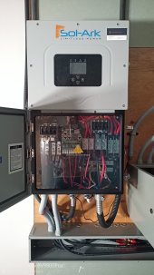
Hey guys just finished my first install.

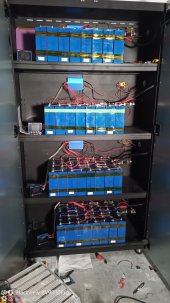
4 banks lifepo4 280AH cells

Solark 15K

4 chargery BMS

10700 watts bifacial solar currently. Govt grant for 5000 more in 6 months or so. Wired in anticipation for that. Pictures of array to follow when there is daylight.

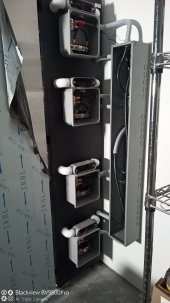
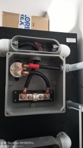
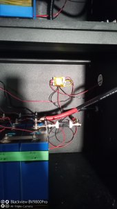
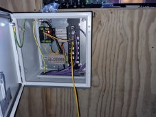
I tried to keep it as safe as possible. 300A tclass fuses. TR contactors used in common with chargery and TE contactors with buck converters for power. Nader breakers from signature solar rated at 200A each. 300A bus bars. My main service is not really heavy electrical. Ac mini splits will be the biggest loads. Heat, hot water, dryer are all propane currently. This is a new house build built really efficient to almost passiv standards. Slab on grade. Need to cleanup wiring in the battery cabinet yet but it's in the wee morning right now!

Enjoy and let me know if something looks off. Still learning here and I'm not an electrician!

edit to show video:

Off gridIMG_20220821_002606.jpg
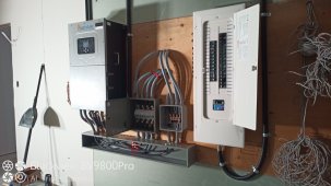

IMG_20220821_002650.jpg

IMG_20220821_002659.jpg

IMG_20220821_002708.jpg

IMG_20220821_002714.jpg
IMG_20220821_002635.jpg
 
Last edited:
Looks very good.
Just needs those extra panels and it will be a complete killer system.
 
Sounds like it's time to switch some of the propane appliances to electric
Great in theory. But we get -40F here in Canada where I live so it's a balancing act lol. Otherwise I'd need 30k solar or more and triple the batteries for overnight heat lol. I also have a woodstove though so that I don't need the propane boiler add often.
 
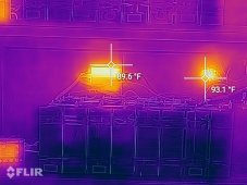
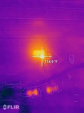
Are there better options for convertering the 48V to 12V other than these buck converters. They seem to get hit at 104F or so. flir_20220821T131914.jpg
 

Attachments

  • flir_20220821T131840.jpg
    flir_20220821T131840.jpg
    677.4 KB · Views: 4
I'm using one of these https://www.aliexpress.com/item/32301052147.html
I only have a tiny load on it at the moment, but it is completely cold to the touch.

View attachment 107809
i'm going to get one of those for sure, i'm not comfortable with the heat generated by this little one, different if I was home 24/7 to monitor it, but i'm going for super safe! so i dont have to worry!


just in the process of top balancing each pack one by one from the solar using the bms, the bms functions perfectly, cutting the contactor when it reaches set points, so far impressed, I was worried by all the negative feedback from chargery but in this setup with the optocoupler it seems to be working great!
 
Thanks for the great feedback guys none of this would have been possible without this forum honestly!!
 
Thanks for sharing. Sound like you are very proud and happy with your system. Engineer 247 on You Tube seems to feel the same about all the installations that he has done with the Sol-Ark 15 KW hybrid inverter for himself and his customers.

My situation is unique, since I'm dealing with an existing system with (3) 5 KW Fronius Primo GT inverters. However, the Sol-Ark will accept 3 strings of solar panels, so I should be able to parallel my six strings into 3 strings.

My Fronius Primo are UL1741 and can be AC coupled, but not rated to modulate the output. If I only use the Sol-Ark 15 KW, I would basically have a normal new installation of one new inverter versus a nightmare of a new inverter trying to control existing inverters. I like redundancy, but I think probably the KISS method is best: KEEP INVERTERS SETUP SIMPLE
Definitely loving it so far!

I should have top balanced my batteries as it's a pain to do it now. But I'm top balancing one bank at a time in the evenings.

You can see more of my setup here:

 
Hello

I have 32 280Ah batteries and 10Kw solar, and Sol-ark 15K . Can you educate me on why you need the opto coupler and disconnect feature you installed on each battery bank? The Class T fuses for safety I fully understand, but I am confused why the contactor is needed and what purpose it serves.

Last question that you may or may not be able to answer. I am testing my 15K Sol-ark with grid only connected, no solar, no battery, with a transfer switch to go back to grid direct if/when needed. When I flip the transfer switch from grid to solark, everything stays on in home, but the solark display says OFF, and I don't see any power consumption from grid or load. The main power from grid is fed directly into the solark, and then the entire home load of 200A is on the load output. I would expect to see power based on the CT's installed , but as of now the sol-ark is just passing the power through, and not reporting any power information.

I can turn the solark on and off with the button on the side, nothing changes, and the DC switch is off, as well as the DC breakers (no batteries yet installed) just confused why I don't see any power. Image attached.No consumption image.png
 
Hello

I have 32 280Ah batteries and 10Kw solar, and Sol-ark 15K . Can you educate me on why you need the opto coupler and disconnect feature you installed on each battery bank? The Class T fuses for safety I fully understand, but I am confused why the contactor is needed and what purpose it serves.

Last question that you may or may not be able to answer. I am testing my 15K Sol-ark with grid only connected, no solar, no battery, with a transfer switch to go back to grid direct if/when needed. When I flip the transfer switch from grid to solark, everything stays on in home, but the solark display says OFF, and I don't see any power consumption from grid or load. The main power from grid is fed directly into the solark, and then the entire home load of 200A is on the load output. I would expect to see power based on the CT's installed , but as of now the sol-ark is just passing the power through, and not reporting any power information.

I can turn the solark on and off with the button on the side, nothing changes, and the DC switch is off, as well as the DC breakers (no batteries yet installed) just confused why I don't see any power. Image attached.View attachment 114718
The optocoupler is specific to the chargery BMS so that I can use it as a common port BMS. Common port meaning the same wire does the charging and the discharging control. Because the BMS has four wires to trigger relays I needed to turn that into a common port type of configuration.

As far as your on grid questions I cannot help you there. Off grid here and I am using the grid as my generator input and the gen as the smart load output
 
I don't imagine that those plumbing elbows with such a short bend radius would meet the CEC.
 
I don't imagine that those plumbing elbows with such a short bend radius would meet the CEC.

That I can't comment on. It was inspected by the office of fire commissioner and passed. The only thing I had to do that's not pictured is ground each conduit metal wire Chase to the ground in panel with #6 ground wire
 
I am testing my 15K Sol-ark with grid only connected, no solar, no battery, with a transfer switch to go back to grid direct if/when needed. When I flip the transfer switch from grid to solark, everything stays on in home, but the solark display says OFF, and I don't see any power consumption from grid or load. The main power from grid is fed directly into the solark, and then the entire home load of 200A is on the load output. I would expect to see power based on the CT's installed , but as of now the sol-ark is just passing the power through, and not reporting any power information.


If there are no solar or batteries connected to the Sol-Ark inverter 15, it should simply default to the bypass mode as you described. I would think in bypass mode, the Sol-Ark is not going to report anything and probably would show off as you described. The only reason that I can think of for the CT not to show power, is if by chance you have connected it over 2 wires and they cancel each other out, which would show zero.. Test your CT on something else and make sure it is working ... sometimes it is something as simple as a dead battery or wrong setting.
 
The optocoupler is specific to the chargery BMS so that I can use it as a common port BMS. Common port meaning the same wire does the charging and the discharging control. Because the BMS has four wires to trigger relays I needed to turn that into a common port type of configuration.

As far as your on grid questions I cannot help you there. Off grid here and I am using the grid as my generator input and the gen as the smart load output
Hello.. Ok I am not familiar with the chargery BMS. I will be using a JK BMS
If there are no solar or batteries connected to the Sol-Ark inverter 15, it should simply default to the bypass mode as you described. I would think in bypass mode, the Sol-Ark is not going to report anything and probably would show off as you described. The only reason that I can think of for the CT not to show power, is if by chance you have connected it over 2 wires and they cancel each other out, which would show zero.. Test your CT on something else and make sure it is working ... sometimes it is something as simple as a dead battery or wrong setting.
OK , Thanks... the CT I am describing are the ones supplied with the Solark and surround L1 and L2, then have twisted pairs that connect to the solark so it can monitor the current that passes through the ring. There are no batteries, and my understanding is if I installed them pointing the wrong direction I would get negative current instead of positive current measurements. It may be as simple as you say, if nothing except power and load is connected the Solark may just go into bypass mode and not report anything. I would find that a little strange, but I guess I will have to wait until I connect my AC coupled solar to the generator connection, and then see if it comes to life and starts showing current flow.

CPU
 
Back
Top