diy solar

diy solar

SOLVED: High diff. voltage of 2 adjacent cells at absorption -> defective active balancer

juepi

New Member
Joined
Jun 8, 2023
Messages
16
Location
Austria
Hi folks,

As i managed to fully charge my new and shiny 8S 105Ah LFP battery for the first time today (beside top-balancing), i noticed a strange behavior: as soon as the Victron SmartSolar charger switched from bulk charging to absorption, the cell voltages of the battery started drifting apart rapidly.
First i want to mention that i have very battery-friendly charger settings:
Absorption Voltage: 3.45V/cell --> 27,6V
Float Voltage: 3.35V/cell --> 26,8V
Absorption Time: 1h

Now here's what happened:
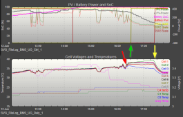
absorption.png

Red arrow --> charger switched to absorption.
Green arrow --> active balancer (5A capacitive) kicked in due to cell diff reaching configured threshold of 40mV
Yellow arrow --> i manually switched on a higher load (added 65W to the previous 25W)

This is the first full charge of the battery since top-balancing it, which is at least 2 months ago. Since then, the battery was partially discharged and within the last 4 days partially charged and discharged.

What seems quite strange to me is that although the balancer was enabled, cell 2 voltage kept rising whereas cell 3 voltage kept falling - my thought on that is that the time span was probably too short for the balancer to do it's job before i "forced" all the cells down to (nearly) float voltage with the higher load?

As a first "counter measure" i've decided to decrease the differencial voltage threshold at which the balancer is being enabled, so my active balancing starts under the following conditions:
* at least one cell has reached 3.4V
* the cell diff between highest and lowest cell is at least 10mV (was 40mV before)
* balancer is disabled as soon as the first cell has less than 3.3V

Meanwhile (2 hours later) the battery pack is back to a cell diff of 4mV at a pack voltage of 26.5V (97% SOC reported by Victron SmartShunt).

Do you think that there is anything i can (or should) do about that? Or is it perfectly normal the way it is?

Any hints on this topic welcome ;)

thanks in advance and have a nice day,

Juergen
 
Last edited:
Just leave it alone at the settings you had and see what happens.

The balancer needs time to do its job.
 
Sitting for 2 months means you lost your top balance. Batteries should not be top balanced until immediately before their commissioning.

Hold at absorption for 24 hours. Monitor for cell convergence.

When cells settle below 3.40V at rest or under load, even imbalanced cells will have very small voltage deviations. Voltage is only an indicator of imbalance above 3.40V (and below 3.1V or so).
 
Sitting for 2 months means you lost your top balance. Batteries should not be top balanced until immediately before their commissioning.
Will keep that in mind for my next battery ?
Hold at absorption for 24 hours. Monitor for cell convergence.
Thanks, just reconfigured the SmartSolar and will give it a try tomorrow (at least for ~6hrs) ?
One more question about this: this should be done with activated balancer, right?

When cells settle below 3.40V at rest or under load, even imbalanced cells will have very small voltage deviations. Voltage is only an indicator of imbalance above 3.40V (and below 3.1V or so).
Ok, that matches my observations so far.

Will keep you updated, thanks!

yours,
Juergen
 
absorption_balance.jpg

Doesn't look very promising after the first 3 hours ?

The balancer seems to have minimized the gap between the already very similar-leveled cells, but the 2 "problem cells" are still slightly drifting apart.
Will let it run in absorption until sundown and try to get an clamp-amperemeter so i can check if my balancer is actually doing something on cell 2 and 3..

yours,
Juergen
 
I would try boosting the voltages while you top balance to push some cells above 3.5v the bigger the delta between the cells the faster the balancer will work.

Once you’re happy with how the cells are balanced, then lower the voltages back down to you’re cell friendly settings.
 
View attachment 152715

Doesn't look very promising after the first 3 hours ?

The balancer seems to have minimized the gap between the already very similar-leveled cells, but the 2 "problem cells" are still slightly drifting apart.
Will let it run in absorption until sundown and try to get an clamp-amperemeter so i can check if my balancer is actually doing something on cell 2 and 3..

yours,
Juergen

Patience. Low and slow.
 
Patience. Low and slow.

If there's something i don't have, it's patience :ROFLMAO:

No seriously. Cell 3 is at a constant voltage and cell 2 is still rising a bit every hour.. i find this very strange and i'd guess my balancer isn't working, or does this make any sense to you?
Sadly i can't source a clamp-ampmeter short-termed somewhere to verify the current running through the balancer wires..

However, i will gather all patience i can find and keep the pack at absorption voltage over night, let's see what happens tomorrow morning.

Thanks everyone for your help, i'll keep you updated.

yours,
Juergen
 
Most chargers, as they approach absorb voltage, will have some drop off in in their bulk constant charging current. It is a factor of feedback control as they transition from constant current regulation to constant voltage regulation.

For the 'blue cell' to drop in voltage under charging it has to be subjected to lower charging current which results in less overpotential voltage boost on cell AND the cell is not yet fully charged.

Since all cells are in series, all cells are being subjected to the same lower charging current. Cells fully charged will have higher overpotential voltage and surface charge build up so their voltage does not drop at the lower charging current. Once fully charged, even a small charging current can cause a cell to continue to rise in terminal voltage to point it trips overvoltage limit on BMS.

From the last picture, it appears you have start of balancing set at 3.45 vdc. The middle grouping of cells says the charging current is equal or less than the balancing dump current capability of the BMS.

Since each BMS sense wire is shared between two cells, it is possible a poor bus bar connection can be the problem, if the two cells that share the same sense wire is 'green' and 'blue' cells. Since the cells are labeled '2' and '3', this is a possibility.

The fact that 'green' cell is over the balance voltage by almost the same delta voltage the 'blue' cell is under balance voltage lends suspicion to poor bus bar connection.

'Blue' cell dropping slightly below 3.40v says it is not quite fully charged yet.

When there is excessive voltage drop across the bus bar due to poor connection, the side of bus bar with sense wire will read lower cell voltage and cell with poor bus bar connection in series will read a greater cell voltage.

The 'green cell' may also have the BMS balance dump for that cell not working because of a burned-out dump resistor or balance load enable transistor being defective open.

The center grouping of cells says the present charging current is low enough to be totally dissipated by balancing dump current capability. All cells should have the same balancing dump current capability, so there should not be a runaway voltage on 'green' cell with the same charge current the middle cells are also getting.
 
Last edited:
Most chargers, as they approach absorb voltage, will have some drop off in in their bulk constant charging current. It is a factor of feedback control as they transition from constant current regulation to constant voltage regulation.

For the 'blue cell' to drop in voltage under charging it has to be subjected to lower charging current which results in less overpotential voltage boost on cell AND the cell is not yet fully charged.
In that relation i want to mention that there is actually no charging current at all since the SmartSolar charger switched to absorption mode. I have also disabled the loads (only a very minor load of ~0.5W is active -> MCU reporting data over WiFi).

From the last picture, it appears you have start of balancing set at 3.45 vdc. The middle grouping of cells says the charging current is equal or less than the balancing dump current capability of the BMS.

The 'green cell' may have the BMS balance dump for that cell not working because of a burned-out dump resistor or balance load enable transistor being defective open.
I have disabled balancing on the Daly BMS (balancing done by an external 5A capacitive balancer), but as mentioned, i'd also assume that it doesn't work correctly.
I am concluding this because the center grouping of cells says the present charging current is low enough to be totally dissipated by balancing dump current capability. All cells should have the same balancing dump current capability, so there should not be a runaway voltage on 'green' cell with the same charge current the middle cells are also getting.
To be honest, i'm not sure if i understand you correctly, imho:
- there is (basically) no external charging current, just the charger keeping the cells at the high voltage level (3.45V)
- due to this the imbalance of the cells show up, as obviously cell 3 has a significantely lower SOC and cell 2 a higher SOC than all other cells
- the balancer should charge cell 3 by draining cell 2 (basically), which does not seem to happen

This is the current state:
2023-06-13 18_46_16-Home, Sweet Home.png

thanks,
Juergen
 
In that relation i want to mention that there is actually no charging current at all since the SmartSolar charger switched to absorption mode. I
Absorb mode does not mean there is no charging current. There usually is some charge current in absorb mode until current tapers down or absorb mode times out causing charger to jump to float mode. (Unless you have absorb voltage set lower than 3.4v times number of series cells)

Disconnect the cap balancer and enable BMS balancer, or a different balancer. Daly BMS will not enable balancing unless it detects charging current so you may have to discharge battery a bit first.

My guess is one or more of the capacitors in balancer has dried out its electrolyte from constant heating, dropping it capacitance value to a low capacitance.
 
Last edited:
Absorb mode does not mean there is no charging current. There usually is some charge current in absorb mode until current tapers down or absorb mode times out causing charger to jump to float mode. (Unless you have absorb voltage set lower than 3.4v times number of series cells)
Ok i see, what i meant was: i could not see (monitor) any charging current - the SmartShunt permanently reported 0W battery power (or even a little discharge) after about 15 minutes after absorption mode started.
Disconnect the cap balancer and enable BMS balancer, or a different balancer. Daly BMS will not enable balancing unless it detects charging current so you may have to discharge battery a bit first.

My guess is one or more of the capacitors in balancer has dried out its electrolyte from constant heating, dropping it capacitance value to a low capacitance.

Agreed, maybe defective cable / connector / PCB trace etc. I also got the hint from a friend of mine that it is very suspicious that 2 adjacent cells "mirror" their behaviour around the "centered" good cells (cell 2 exactly the same voltage too high as cell 3 is too low), which also indicates a balancer issue, which seems very likely to me.

Just because i'm curious: could you explain your suggestion to enable the minimal 20mA passive Daly balancer? Could it do really any good on an 105Ah setup?

I've just ordered a new balancer and i'll check the wiring as soon as I've got time to disassemble the battery from the box.

Thanks for your help on this issue!

yours,
Juergen
 
Just because i'm curious: could you explain your suggestion to enable the minimal 20mA passive Daly balancer? Could it do really any good on an 105Ah setup?

1) 20mAh is better than the nothing you're getting now.

2) 20mA * 24h = 0.48Ah

That's enough to maintain the balance of healthy cells.

I've seen "runner" behavior with as little at 0.1% variation in SoC at the top. 0.48Ah is 0.5% deviation in capacity. That's something you should see on cell voltages.

Can the DALY balancer be set to balance even if there is no charging?
 
Can the DALY balancer be set to balance even if there is no charging?

Afaik no, because it "balances" the cells by actually "burning" charging current from cells with over voltage.

But concerning the rest, you're right of course, 20mA is better then nothing. However, i have to check the configuration abilities of the Daly Balancer (on/off voltage thresholds), i definitely don't want to have this thing running all of the time ;-)

yours,
Juergen
 
Many BMS's require charge current to be detected to balance dump.

The reason is the balancing is screwed up by large inverter load currents. By only allowing balancing when charging you prevent balance cell voltage detection during random large inverter load current.

When start of balancing is set at 3.4v or greater it pretty much assures there will only be balancing during charging because any inverter load will quickly drop cell voltage below 3.4 vdc. No charge current detection is really needed.

BMS's detection accuracy of low battery current is not great so you may have to push a couple of amps of minimum charge current for the BMS to recognize there is charging and enable balancing.

If BMS only balance dumps when there is charging it needs a special override mode to cover situation where a BMS cell overvoltage shuts down charging. BMS terminates charging due to overvoltage cell, but you want to bleed overvoltage cell down to timely reset BMS charging shutdown.
 
Can you share a picture of that active balancer and how you have it connected?

IMO it doesn’t seem right that voltages are all wrong once activated.
 
Many BMS's require charge current to be detected to balance dump.

The reason is the balancing is screwed up by large inverter load currents. By only allowing balancing when charging you prevent balance cell voltage detection during random large inverter load current.

When start of balancing is set at 3.4v or greater it pretty much assures there will only be balancing during charging because any inverter load will quickly drop cell voltage below 3.4 vdc. No charge current detection is really needed.

BMS's detection accuracy of low battery current is not great so you may have to push a couple of amps of minimum charge current for the BMS to recognize there is charging and enable balancing.

If BMS only balance dumps when there is charging it needs a special override mode to cover situation where a BMS cell overvoltage shuts down charging. BMS terminates charging due to overvoltage cell, but you want to bleed overvoltage cell down to timely reset BMS charging shutdown.

These sound like the reasons why i don't want to bother using the BMS balancer, but to have a dedicated (switchable) active balancer so i have full (software) control on the conditions when to balance ;)
 
Can you share a picture of that active balancer and how you have it connected?

IMO it doesn’t seem right that voltages are all wrong once activated.
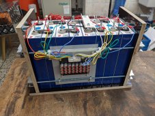
PXL_20230413_175414423.jpg

Here you go, should be fine imho.
There is another reason which makes a defective balancer more plausible: since the active balancer was connected, it was never activated (which means the 2 "RUN" pins shorted; that extra wire is not connected in the picture), but when i got my first full charge, cells 2 and 3 already were massively unbalanced as it seems.
Will get my new balancer on saturday, then i can tell for sure what's wrong (hopefully!).

yours,
Juergen
 
Last edited:
Back
Top