diy solar

diy solar

SP6548 and SG48100M BMS configuration guidance needed

tomlos

New Member
Joined
Dec 18, 2023
Messages
16
Location
East Texas
Hey all. Trying to get the BMS working between the 6500w SP6548 and SG48100M (for now it's just one) and running into documentation and just figuring it out. Does anyone have something handy to share? I tried following the directions but wondering if I had just used the wrong port on the battery. I went from the Li-ion port on the inverter to the RS485A port on the battery (i will be adding two more batteries soon), set the battery type to Pylon, and also set the first dip switch to on per the documentation. The inverter faulted with a 61 error, and i also tried with dip-switch as default. So I set it back to the AGM which is by default and it works for now, but want to get BMS working ASAP.

Can someone provide some guidance on how to do this with a single battery, and what I will need to do on the other two I am going to be adding shortly?

Thanks in advance everyone, appreciate it and glad to have found this forum!
 
I have the same set up and I'm having the same issue. When I followed the steps in the manual I get an error 61. I set it back to AGM for the time being as that works.
 
Hey all. Trying to get the BMS working between the 6500w SP6548 and SG48100M (for now it's just one) and running into documentation and just figuring it out. Does anyone have something handy to share? I tried following the directions but wondering if I had just used the wrong port on the battery. I went from the Li-ion port on the inverter to the RS485A port on the battery (i will be adding two more batteries soon), set the battery type to Pylon, and also set the first dip switch to on per the documentation. The inverter faulted with a 61 error, and i also tried with dip-switch as default. So I set it back to the AGM which is by default and it works for now, but want to get BMS working ASAP.

Can someone provide some guidance on how to do this with a single battery, and what I will need to do on the other two I am going to be adding shortly?

Thanks in advance everyone, appreciate it and glad to have found this forum!
The first dipswitch should be set 0100 for master battery. 0000 or 1000 will not work correctly.
 
The first dipswitch should be set 0100 for master battery. 0000 or 1000 will not work correctly.
Interesting, so I have three batteries (or will as of this weekend) and the instructions I had received from SGP support is the below

"Please dial the ADD1 on the battery 1 to ON, dial the ADD2 on the battery 2 to ON, dial the ADD1 and 2 on the battery 3 to ON."

So 1000 for the first, 0100 for the second and 1100 for the third it appears. I haven't not validated this yet, but will try this weekend.
 
Interesting, so I have three batteries (or will as of this weekend) and the instructions I had received from SGP support is the below

"Please dial the ADD1 on the battery 1 to ON, dial the ADD2 on the battery 2 to ON, dial the ADD1 and 2 on the battery 3 to ON."

So 1000 for the first, 0100 for the second and 1100 for the third it appears. I haven't not validated this yet, but will try thi
Yup
Interesting, so I have three batteries (or will as of this weekend) and the instructions I had received from SGP support is the below

"Please dial the ADD1 on the battery 1 to ON, dial the ADD2 on the battery 2 to ON, dial the ADD1 and 2 on the battery 3 to ON."

So 1000 for the first, 0100 for the second and 1100 for the third it appears. I haven't not validated this yet, but will try this weekend.
Yup, odd since that's the only way I got it to work
 
The first dipswitch should be set 0100 for master battery. 0000 or 1000 will not work correctly.
Dang, I forgot to try what you have in your reply. So If I am trying your advice here that worked for you, 0100 would be the first battery, and the second and the third would be set to what?

Now makes me want to drive three hours back to my ranch and try this again lol
 
Running into a simliar issue with 2x sp6548 & 4x SG48100M - any luck with getting it configured?

Thanks
 
Actually as an update here is what their support sent over just now:


Thanks for reaching out to us.

Please follow the following steps to build BMS between the inverter and battery for a try.
1. The wire sequence of the two ends of the communication cable between the inverter and the battery should be correct. We recommend using the communication cable configured for the SP6548 inverter, there are indications at both ends of this cable, please be careful not to insert it backward.
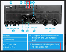
2. This communication cable needs to be connected to the right port, the battery end should be plugged into the RS485A interface. The Inverter end should be plugged into the port 16
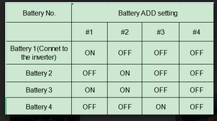
3. Please dial the ADD as attached picture
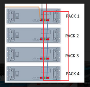
4. Please connect the RS485 battery communication cable as attached picture(From battery RS485 B port to RS485 C port)
5. Select PYL in item 14 "Battery type" of LCD Setting of on one SP6548 inverter, and make sure the setting is successful. The other inverter set "User-defined" in item 14 "Battery type"

After completing the above steps, please turn off the inverter. Then turn on the inverter again to see if the inverter has successfully communicated with the battery.
Here is a video for your reference, please check.

1704161342905.png
1704161352973.png
1704161364113.png


So to recap -
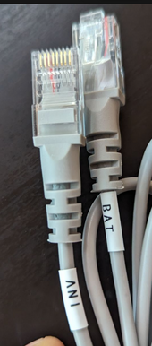
You need the special cable they send with the inverter

1704163095140.png
as you can see its like a cross over cable that is not terminated like a normal ethernet.


From port 16 on the inverter > RS485A on Battery 1
Battery 1 port RS485C to Battery 2 port RS485B
Battery 2 port RS485C to Battery 3 port RS485B
Battery 3 port RS485C to Battery 4 port RS485B

after doing this the battery icon flashes on my inverters, which seems to indicate a good connection
 
Last edited:
Actually as an update here is what their support sent over just now:


Thanks for reaching out to us.

Please follow the following steps to build BMS between the inverter and battery for a try.
1. The wire sequence of the two ends of the communication cable between the inverter and the battery should be correct. We recommend using the communication cable configured for the SP6548 inverter, there are indications at both ends of this cable, please be careful not to insert it backward.
2. This communication cable needs to be connected to the right port, the battery end should be plugged into the RS485A interface. The Inverter end should be plugged into the port 16
3. Please dial the ADD as attached picture
4. Please connect the RS485 battery communication cable as attached picture(From battery RS485 B port to RS485 C port)
5. Select PYL in item 14 "Battery type" of LCD Setting of on one SP6548 inverter, and make sure the setting is successful. The other inverter set "User-defined" in item 14 "Battery type"

After completing the above steps, please turn off the inverter. Then turn on the inverter again to see if the inverter has successfully communicated with the battery.
Here is a video for your reference, please check.

View attachment 186327
View attachment 186328
View attachment 186329


So to recap -
You need the special cable they send with the inverter

View attachment 186342
as you can see its like a cross over cable that is not terminated like a normal ethernet.


From port 16 on the inverter > RS485A on Battery 1
Battery 1 port RS485C to Battery 2 port RS485B
Battery 2 port RS485C to Battery 3 port RS485B
Battery 3 port RS485C to Battery 4 port RS485B

after doing this the battery icon flashes on my inverters, which seems to indicate a good connection

Fantastic.. I seem to be missing that INV and BAT labeled cable unfortunately. I reached out to them and once I get that replaced the instructions are very similar to what I have been doing and what they sent you. The YT video is helpful too. You'd think they would get their act together and post some basic videos like this on commonly asked questions to make it easier for us..... lol.
 
Back
Top