diy solar

diy solar

spd means the dc core floats until a surge hits?

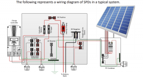
Looking at page 4 figure 1.2 of https://www.midnitesolar.com/pdfs/SPD_Installation_Manual.pdf
I see that the only connection between the dc negative busbar and the ground busbar is through the spd.
Since the spd is just some varistors which will not be conductive at normal voltages, I take that to mean the system is floating until there is an induced surge.

Am I understanding that correctly?

@Will Prowse
It’s probably actually big TVS diodes , the graph looks very “ TVS “ like

Usually TVS just short power and ground together ( ie negative ) floating or not. This tends not to be useful for externally earth referenced induced voltages , so some configurations short to earth , in this case I suspect there are surge diodes protecting both positive and negative lines
 
Are you referring to this drawing ? (below, hopefully)

The green SPD wire is GND and is connected to the GND bus bar. The DC negative is connected to the battery and PV negative but is not connected to GND at all in this drawing.

The PV negative and PV positive are connected to the two halves of the SPD for use as a common-mode lightning arrestor. Normally, during a lightning, both positive and negative lines will raise up at the same time and so is the reason for both lines to be connected to the SPD.
This way, the insulation in the equipment between its chassis or GND, will see less of a chance of internally arcing to the other conductors.

The voltage of the MOVs have to be lower than the equipment's Hi-Pot test voltage.

The negative (PV and battery connection) won't necessarily be grounded in this drawing. The GND/Green of the SPD MUST be grounded though.

The SPD has MOVs in it which, depending on the voltage rating of the SPD, will clamp the positive and negative to the turn-on voltage of the MOV.
MOVs are kind of like HV Zener diodes but polarity independent.

boB


1661668901105.png
 
Is there a way to use the SPD properly and have the negative busbar voltage referenced to the planet during normal operation?
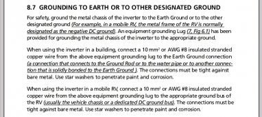
I wouldn't recommend grounding any part of the DC system (positive or negative), unless specifically instructed to do so by the manufacturer.
In most current products available, this is a big no no.
Unless it's a mobile installation.
I personally wouldn't, even then.
 
I wouldn't recommend grounding any part of the DC system (positive or negative), unless specifically instructed to do so by the manufacturer.
In most current products available, this is a big no no.
Unless it's a mobile installation.
I personally wouldn't, even then.
Hope you don't mind my asking, why not?

If I'm not mistaken many of the system diagrams I see here would have the grounding lug on the inverter/charger connected to the negative busbar which would reference the negative busbar to the planet, right?
 
It depends on what system you are installing.
Many now have surge, ground fault, and possibly lightning protection built in. Grounding the circuit negates these features. And can also cause error codes and possibly damage equipment. Some systems also have AC ripple voltage present on the DC circuits. This can be a life safety Hazzard.
This is why it's important to follow the manufacturers instructions for whichever equipment you choose to install.
 
I've thought about it some more and here is my current understanding.

The DC SPD has 3 wires.
  1. Connects to the positive busbar to protect the positive leg against surges.
  2. Connects to the negative busbar to protect the negative leg(if it is not explicitly grounded) against surges and to power the LED status light.
  3. Connects to the ground busbar so that the SPD has some safe place to dump the surge.
So even if the the negative busbar is grounded the SPD will still be connected to it in order to power the status LED.
 
But doesn't that mean that if the negative busbar is bonded to the ground busbar and a surge occurs on both legs that a short circuit occurs?
 
But doesn't that mean that if the negative busbar is bonded to the ground busbar and a surge occurs on both legs that a short circuit occurs?

Nahhh. Not for lightning, most likely. (?)... The negative being grounded means that what voltage difference there would have been between the chassis of the protected equipment and its negative, would be closer together in voltage which "shouldn't" hurt anythng I would think.
Then, the positive would also be limited in voltage rise difference because of its MOV clamping voltage with reference to the chassis GND of the equipment.

There might be a situation where that wouldn't be a good idea to ground the negative ?. Possibly the negative PV line being grounded might enable the lightning to be more easily conducted to that line but would it hurt anything ? I don't know.

Then again, lightning is so weird, anything could happen I suppose. A direct strike to the PV or AC grid coming in would probably be the worst case. Just being a close strike though can make voltages rise a lot.
boB
Lastest iteration in understanding... its not really a short circuit because the voltage has to be high enough to trigger the MOV=metal oxide varistor.
 
Yes, a MOV in an SPD does not present a short. It would be easier for the MOV if it were a short though because then it wouldn't have to dissipate power as heat. Zero volts times some high current = zero watts. But MOVs clamp the voltage. The higher the current that it has to clamp, the higher its voltage goes. And the higher its power dissipation. An SPD 300 for instance actually starts clamping at around 475 V DC I think ? it is designed for a 300V circuit, basically.

The MOV in an SPD or other surge protection device tries to limit the voltage across it. But when the MOV conducts at that clamping voltage, it has to dissipate power for as long as the surge is present. The bigger the MOV, the more energy (Joules) it can handle at one time because it takes time to heat up. The MOVs in the MidNite SPDs are 35mm which is pretty big. MOVs inside equipment are usually quite small but can help when short lightning hits are nearby. But MOVs also degrade as time goes on because of whatever material they use inside. They like to keep their recipes a trade secret.

So, a MOV experiences a power dissipation of the voltage it clamps at times the current through it like any resistive device. Longer amount of time with power means more energy in the MOV.

This limitation is why any surge protective device using MOVs can't limit things like high voltage AC or DC and is really limited to short bursts like lightning.
 
Back
Top