diy solar

diy solar

SPF 6000 ES plus. 120 vac Neutral to ground voltage on output load panel fed from solar edge auto transformer

Bigbadben

New Member
Joined
Sep 23, 2022
Messages
12
So I just replaced my SPF 5000 ES unit with a new SPF 6000 ES plus. The issue is the 6000 es is reading a load on the output LCD of 12% with just the auto transformer connected and with all load panel breakers off. I am measuring 120 vac from neutral to ground so this is where the issue is. Does anybody know how to rectify this problem as my 5000 es plus worked perfectly. I am unsure as to whether the 6000 es plus requires a bonding screw to be removed. I have asked Growatt technical support about this but they have not replied.

Any help would be appreciated as I am offline now until I get this sorted out.


Thank you. Ben
 
You went from a EU single phase to an AT to a split phase to an AT. In your prior setup, the only proper place would have been at the AT or the AC panel.

You can only have one N-G bond.

The default behavior of inverters is to supply the N-G bond when invertering and break it when on grid, so if you have an N-G bond in either the AT or the panel, you need to break it at the inverter.
 
Ok that is useful information. Thank you ! The question is does the 6000 es plus have a bonding screw that needs to be removed like the 5000 es and is that the issue.....a bonding screw in the 6000 es. My 5000 es works perfectly with exactly the same wiring I have now.
 
Ok that is useful information. Thank you ! The question is does the 6000 es plus have a bonding screw that needs to be removed like the 5000 es and is that the issue.....a bonding screw in the 6000 es. My 5000 es works perfectly with exactly the same wiring I have now.

I can't answer that. I would expect so.

You can't reasonably compare the two systems. The 5000ES is a single phase EU system, and it MUST be unbonded when incorporated into a North American split phase system, or undesirable things happen. The 5000ES REQUIRED you provide an alternate N-G bond elsewhere. You could try breaking that other bond and seeing if it resolves your issue.
 
I'm sorry but when will people learn ?
It is now cheaper to buy the proper equipment and soooo much easier.
 
Ah true. Sorry for half of the insult ?
BTW you have the best fruit in the world ?
When I visit your country again I will bring you a proper inverter ?
 
Thanks very much Quattrohead. It's impossible to find qualified electrical people in the jungle. That's my problem.

It's been a bloody nightmare getting my original SPF 5000 working properly, I finally figured that out myself.

Buying and importing anything over $1k here is so difficult and you if you do, there is so much paperwork and tax you have to pay it's just not worth the expense or trouble. Hence my problem.

The SPF 6000 here is over 2k without taxes and everything else.

I am sure I can get this to work with my existing electrical setup which is why I reached out to the forum.

Thank you.
 
I'm not familiar with the spf6000ES plus.
But it's also a single phase EU unit. So the issue is probably the internal N/G bond.
But I don't know what would be required to defeat it.
Not sure if it's a single screw, like the 5000ES or not.
 
I was told by technically support in the USA that the unit is identical to the 5000 es but with increased capacity. Two mppt inputs etc etc...which is really what I need as my arrays face east and west. The 6000 es is the perfect solution for my application. I now have the unit connected to grid power and the bond is broken so that means there is a bonding screw that needs to be removed I believe. What is odd is that the grid input shows a current draw of 1.5 amps which should be zero as I have plenty of PV capacity. The KW input shows zero on the display.
 
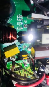
Ok so the only screws with a ground symbol next to them are on the mppt board. I cannot see any on the main PCB. One of the screws can be accessed through a hole in the plastic shroud as if you could easily remove that screw...or why have the hole in the plastic shroud. Please see attached photo. Any thoughts?
 

Attachments

  • IMG_20231019_144201.jpg
    IMG_20231019_144201.jpg
    608.9 KB · Views: 9
Yeah, I looked at every screw on the main PCB but none have the ground symbol next to them like the mppt board. I just received a message from James at Growatt USA and he seems to think this model has dynamic bonding.

Removing both the screws on the mppt PCB made no difference to the issue.
 
I'm sure that it has dynamic bonding.
Because it can operate off grid and has grid pass-through.
The bypass relay will disconnect from the grid and simultaneously bond the neutral to ground.
You have to figure out where that relay gets its ground from. And defeat it.
 
Thank you Tim, I very much appreciate your input. Figuring out how to do that might be a challenge. Have a good evening. Cheers Ben.
 
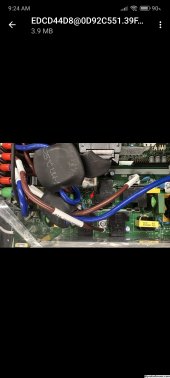
I thought I would provide the information on the N-G bonding screw that needs to be removed on this Growatt inverter. The information was provided by Growatt China. They have been very supportive and helpful. My system is working perfectly.

Thank you. Ben
 

Attachments

  • Screenshot_2023-10-20-09-24-59-952_com.google.android.gm.jpg
    Screenshot_2023-10-20-09-24-59-952_com.google.android.gm.jpg
    217.3 KB · Views: 25
Yep that was the area that we were expecting the screw to be in although I'm surprised that growatt are still falling for this silliness.. actually I'm not.
Very happy that you got this sorted.
 
Back
Top