diy solar

diy solar

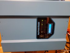
Strange readings testing voltage on an all in one unit

Odjono

New Member
Joined
May 4, 2022
Messages
29
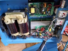
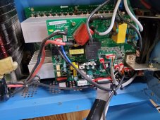
I installed an all in one unit in an rv of mine mppt charger inverter grid tie and discovered crazy volt readings on ac out but only when it's in pass through mode. In inverter mode running off batteries I have normal 120v one neutral one hot. IN pass through mode it looks like 120v split phase about 60v on neutral and 60v on hot and is been running a microwave fridge? Was testing my fridge thermostat when I noticed it. How is it even possible without frying the circuit board in my microwave.
 

Attachments

  • 20220504_182806.jpg
    20220504_182806.jpg
    340.1 KB · Views: 19
  • 20220504_182755.jpg
    20220504_182755.jpg
    326.1 KB · Views: 19
What are the attachments for? Should we guess what unit this is?
What is a microwave fridge?
Do you feel confident operating a voltage meter?
 
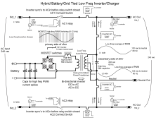
You are likely only feeding 120vac across L1-L2 AC input. These inverters do not have a separate AC input neutral connection. They normally only take 240vac input. The inverter output transformer acts like an auto transformer in pass-through giving the center 120vac neutral.

I would not expect the AC input pass through relays to engage pass through if only 120vac was applied to input.

Some manf. allow 120vac only input from L1 input to neutral output but I don't think AIMS is one of them, if that is AIMS inverter.

There are 120vac only models so need to post the model number.
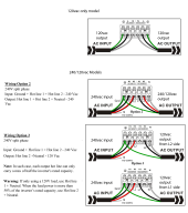
AIM wiring options.pngLF hybrid inverter block diagram (3).png
 
Last edited:
I solved it was strange but I had ran an extension cord with a broken ground prong I replaced it and readings went back to normal. Microwave and fridge lol. The first diagram was the same as mine
 

Side question after reading the diagrams: why you have different options for 240V split phase and how do you choose one over the other?
I suspect if you have 240V split phase from a generator and you need 240V split phase out of the inverter that one you'd choose Option #2 above?

Is this correct?
 
Side question after reading the diagrams: why you have different options for 240V split phase and how do you choose one over the other?
I suspect if you have 240V split phase from a generator and you need 240V split phase out of the inverter that one you'd choose Option #2 above?

Is this correct?
It is manf. diagrams but I added std wire colors. Input must be 240vac as these 240/120vac split phase models do not allow 120vac only inputs.
Some manf. like Magnum, allow 120vac only input via L1 side to output neutral. When they detect this 120vac only input they do not close the L2 input connect relay side so there will be no AC from inverter transformer showing up on the unused L2 input terminal.

Option 3 is just showing 120vac outputs, either L1 side or L2 side. It does not allow full inverter power output from half side of output transfomer.
 
It is manf. diagrams but I added std wire colors.
@RCinFLA thanks for the reply but i don't think you understood my question. I was asking why the different wiring options under the manual for 240V split phase.

I think I figured it out by now: Option #2 is for 240V split phase in (from Generator) and 240V split phase out (to split phase panel).

Option #3 is for 240 split phase in BUT 120V out.

I have a 240v split phase generator wired to a split phase panel, so I should stick to wiring under Option #2.

Thank you for posting these graphs, very helpful.
 
Back
Top