diy solar

diy solar

Struggling to determine sizing and placement for fuses/breakers

daltons_advantures

New Member
Joined
Aug 18, 2023
Messages
11
Location
United States
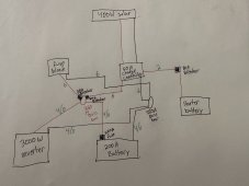
Hey everyone, first post here. I've been reading and watching a lot of videos and I've come up with this rough draft of a diagram thus far.

I know I need a fuse attached to the positive terminal of my solar battery, I'm just not sure what size I need. Is it 200A as thats the capacity of my battery? Do i oversize it by 25%? Also I understand that my battery won't be able to fully utilize the 3000W inverter. I plan on barely using the inverter, however. Is fusing it and wiring it for 175A acceptable?

Also, in terms of the bus bar sizing, I want them sized at 250A for 125% of my 200A battery bank, right?

Thanks in advance anyone and everyone! And my apologies for the poor diagram. Art isn't my strong point.
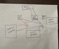
IMG_3154.jpg
 
Fuse at the battery, say 250 amp, MRBF or classT.
At the positive buss bar, fuse for cable to fuse box, 50A, fuse for charge controller 60 amp.
Select cable from this,
Thank you for the response!

My bluesea fuse block is rated at 100A, and I plan to get nowhere near that. That said, 4awg wire and a 100A fuse at the buss bar connection should prove sufficient if I'm understanding the chart correctly, right? The length will be no more than a couple feet.

50A, fuse for charge controller 60 amp
Are you saying use a 60A fuse between my starter battery and the controller?

Thank you again for the help!
 
you saying use a 60A fuse between my starter battery and the controller
No you have a breaker at that point for over current protection.
Fuses/breakers protect the cable and what is on the end of that cable.
To protect the cable from the buss bar to the controller you need a fuse suitable for that cable. The instructions for the controller, (DCC50S?) Suggest suitable fuses/breakers and cable.
My bluesea fuse block is rated at 100A, and I plan to get nowhere near that. That said, 4awg wire and a 100A fuse at the buss bar connection should prove sufficient
That's OK, but if you will never pull 100 amps you can fuse and cable for the expected current, based on experience I suggested 50 amp fuse.

Note your drawing shows 400 watts of solar, if the controller is DCC50S, the maximum panel input volts is 23 volts.
 
No you have a breaker at that point for over current protection.
Fuses/breakers protect the cable and what is on the end of that cable.
To protect the cable from the buss bar to the controller you need a fuse suitable for that cable. The instructions for the controller, (DCC50S?) Suggest suitable fuses/breakers and cable.

That's OK, but if you will never pull 100 amps you can fuse and cable for the expected current, based on experience I suggested 50 amp fuse.

Note your drawing shows 400 watts of solar, if the controller is DCC50S, the maximum panel input volts is 23 volts.
Okay that makes sense. I'll fuse and wire the buss bar to the fuse block for 50 amps.

For the charge controller, I liked that it was sort of a simple all in one unit. I also have a 30 amp PWM controller laying around. Would it be wise to run the solar through the pwm, and the alternator through the DC-DC controller?
 
The MPPT in the controller you have will be OK providing your panel volts don't exceed 23 volts. This means using so called 12v panels that have a maximum voltage around 21 volts, is a parallel connected array.
Do you have panel details?
 
Back
Top