diy solar

diy solar

Stumped on Class T fuse:

Saltyoldcruiser

New Member
Joined
Dec 4, 2022
Messages
49
I'm about to do the final wiring on my 4S 280 AH battery with a 200 amp JK bms. I have double 2 awg wires from my negative on my battery to my BMS and will be using double awg2 wires to a class T fuse between the positive and the main bus bar. My heaviest draw will be a 2000 watt inverter. What size class T fuse should I be looking for?
 
Yes, The fuse will be before the busbar. I was thinking on one 225 amp fuse at the termination of the dual wires. That would make things a lot simpler for me. Thoughts on that? I'm thinking of the dual #2s as a single 1(0). Am I on the wrong track?
 
Yes, The fuse will be before the busbar. I was thinking on one 225 amp fuse at the termination of the dual wires. That would make things a lot simpler for me. Thoughts on that? I'm thinking of the dual #2s as a single 1(0). Am I on the wrong track?
I'm using the dual #2s for the flexibility more than anything, and also because my bms has 2 terminals to spread the load.
 
I modified an extra cell bus bar and placed across the two BMS terminals to minimize electrical stress on the circuit board to feed full power to the single terminal.
I did think about that but I'm trying to compact this circuitry into a rather small area. Every component takes up real estate that is kind of scarce. It might just come to that.
 
I did think about that but I'm trying to compact this circuitry into a rather small area. Every component takes up real estate that is kind of scarce. It might just come to that.
But you'd still have 2 wires from the busbar to the bms, correct?
 
The issue is that my bms has 2 terminals for the negative lead from the battery and the bms terminals are M6. I'm reluctant to put one 2/0 cable on a m6 terminal. That, and there's the flexibility of the 2/0 wire. I think I would be fine with 1/0 wire with only 200 amps continuous but that's still a lot to ask of a m6 terminal screw.
Sorry if I am confused here, but the BMS and the dual 2AWG wires are all on the negative side right? From the main neg battery post to BMS to negative bus bar - and no fuses are needed.
The T-class fuse is best close to the main positive battery terminal then leading to the positive bus bar. There is no clear advantage in my mind to using a pair of 2AWG wires vs a single 2/0 wire (which has the same total cross sectional area) on the positive side.
Am I missing something? I don't see the reason the pair of BMS terminals should affect the wire choice to the fuse.

Of note: ABYC states that using pairs of parallel wires is acceptable to lower the voltage drop (not a big deal here with short wires) but that each individual wire should be able to handle the whole load. So that's one vote for a single wire, but may be less critical when not on a boat.
Yeah, this has been something I've stressed over to be honest. I do need to use a paired wire on the negative side because the bms has two terminals and there's not enough room for a single 2/0 terminal on either one. it's designed for paired wires. I do realize that it's not optimal but I'm going to run a pair of awg 2 wires from the bms to the negative terminal where both wires will terminate in a single lug. I've checked the lug and it crimps the pair of awg 2 wires nicely with a Temco hydraulic crimper. I could indeed run a single 2/0 wire from the positive to my class T Blues seas fuse block. The only reason I'm using a pair of awg 2 positive wires is flexibility. There are some tight bends that I'll never get the 2/0 to make. As you stated the cross section of the 2 awg pair is the the equivalent of 2/0. It might actually be a tad bigger than 2/0 so the ampacity is not the issue. I guess that's why we take the precaution of a class T fuse. There are some physical limitations to what I can and can't do and this is the compromise I've somewhat reluctantly accepted. Another point is that while this is a 200 amp bms with capability for a 350 amp surge, I'll be setting it up for a max 175 amps and dialing back that surge to 200. It will never see 200 amps. I don't like running my electronics at near their rated capacity so I bought oversize and will limit the output to something more like what a single 2 awg wire could handle for a brief load.
 
Last edited:
Got it! That all makes sense and seems totally reasonable.
Of note, the Overkill Solar 100A BMSs sometimes comes with 2 pair of 8AWG already soldered to the board - seems silly to remove those and add a little bus bar.
With quality crimps, well torqued connections and relatively short wire runs, you should be good to go!
 
You could also use a single stud terminal that can be mounted and have both of the BMS cables attached to that and single cable the rest of the way. Other option is to use a butt splice where you can insert both of the 7 AWG cables from the BMS into one end and larger gauge on other end.
 
Got it! That all makes sense and seems totally reasonable.
Of note, the Overkill Solar 100A BMSs sometimes comes with 2 pair of 8AWG already soldered to the board - seems silly to remove those and add a little bus bar.
With quality crimps, well torqued connections and relatively short wire runs, you should be good to go!
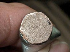
Yeah, I just did a test crimp with a pair of 2 awg wires in a rugged 2/0 lug. The crimp came out very nice. I did cut to check for gaps and it's rock solid. A true gas tight crimp. If there were a cable failure the crimps would be the most likely place and I'm feeling really good about that.
 

Attachments

  • Lug cut with 2 2awg cables.jpg
    Lug cut with 2 2awg cables.jpg
    261.6 KB · Views: 8
You could also use a single stud terminal that can be mounted and have both of the BMS cables attached to that and single cable the rest of the way. Other option is to use a butt splice where you can insert both of the 7 AWG cables from the BMS into one end and larger gauge on other end.
Yeah, the issue seems to be that best practices would not use 2 cables. Short of using a fabricated 2 into one bussbar on the BMS I'm locked into branching to 2 wires at some point. I did a test crimp with a pair of 2 awg wires into a 2/0 lug and it looks fine. I cut it and there are no gaps whatsoever. I'll go with a single 2/0 positive cable to my class T fuse and a double 2 awg cable with a single lug on the battery side and 2 lugs for the bms side. The negative cable will be less than a foot long.
 

Attachments

  • Lug cut with 2 2awg cables.jpg
    Lug cut with 2 2awg cables.jpg
    261.6 KB · Views: 2
Back
Top