diy solar

diy solar

Sudden battery voltage drop, only when epever connected

DaniSe

New Member
Joined
Nov 8, 2021
Messages
33
Recently switched from a 40amp BN series to the 8415 AN on Thursday night after my 40amp was possibly borked due to user error.

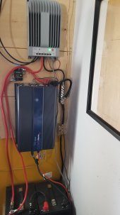
My current setup is four 320w panels (2s2p), the Tracer AN 80 amp mppt, two 100ah SOK batteries in series for 24v, and a 2000W Samlex inverter.

On Friday (first day using new controller), thr PV would still periodically cut out in cold, bright conditions as amps in would rise (was having this issue on the 40a but thought it was the controller) but never any warning light on the indicator. I put shade cloth over panels to limit these conditions while I tried to troubleshoot what was going on. One guess was bad MC4 connections after a severe ice storm, new ones are ordered to see if that solves the cutting out issue.

Saturday during the day was much the same, I was constantly monitoring the charging output on the MT-50 and it was functioning properly so long as the PV didn't cut out. On one such cut I briefly saw the red indicator but it cleared before I got a look at the screen. I fully covered the panels at this point to prevent possible damage to my system.

This evening (sun had been down for hours, all was running as it should), my inverter alarm sounded for a dead battery and the controller indicated 11v from my battery bank. I replaced the battery lead from controller to breaker as reading the manual it seems it was too large. Turned the system back on, and all seemed well though the controller wouldn't auto detect the bank voltage. It read 26v, but all charge parameters were for 12v system. I factory reset, and it seemed to sort itself out.

A few hours later, same alarm. After again turning inverter off and flipping the breaker between controller and battery, I ran the following tests with my multimeter:

-As it was upon shutting down, battery read 11v at terminals
-disconnected everything from bank, battery reads 26v
-separated bank, batteries both read 13v
-reconnected inverter only, battery bank reads 26v / turn inverter on, battery bank reads 26v
-reconnect controller and inverter turning on immediately results in voltage drop.
-reconnect controller only, voltage held at 26v for a minute or so then dropped to 11v again.

It seems anytime the controller is attached to the bank, and any load is applied, the voltage plummets. Any ideas? I am flummoxed, frustrated, and hoping you all may have some suggestions for me after I try getting some sleep...
 
Sounds like a BMS is opening, low voltage protection. Recovers quickly when loads are removed, loads reapplied and voltage tanks and repeats. Charge batteries with grid or generator to full.
320 panels have a VOC of around 47 volts at 25 degC. X 2 plus temperature adjusted can exceed 100 volts. If SCC max VOC is 100 that could be your day time problem. If it is 150 then perhaps you were consuming more than producing.
 
Sounds like a BMS is opening, low voltage protection. Recovers quickly when loads are removed, loads reapplied and voltage tanks and repeats. Charge batteries with grid or generator to full.

Would this be the bms on the batteries? Or is there a similar protection in the controller as well? I ask because the shutdown is not occurring when the battery is attached to the inverter with load. Ground some coffee this morning to test, after turning the inverter on with no load and seeing if there was the voltage drop.

320 panels have a VOC of around 47 volts at 25 degC. X 2 plus temperature adjusted can exceed 100 volts. If SCC max VOC is 100 that could be your day time problem.
The panels reach 83 volts in cold sun (rated VoC is 40.1 each panel) and the controller has 150v max limit

If it is 150 then perhaps you were consuming more than producing.

We had been running this system on the 40a controller with no overuse issues, it would take us three or so days of dark snowy weather to get into 30% territory, and the battery was full late afternoon yesterday so I don't think it is an overconsumption issue.
 
Yes BMS in one of the batteries is disconnecting and it really sounds like low voltage.
Follow up on low voltage - the BMS disconnect for the SOK is at 10.4 / 20.8, and the multimeter is reading at 26.4v when resting . I would have thought that resting voltage would be lower if the battery was depleted enough to trigger the BMS disconnect - is that assumption incorrect? I am still new to a lot of this and have been discovering holes in my understanding.

When observing voltages while testing last night, when the plunge occured the volts would start dropping rapidly from 26 through the low 20s and then the alarm from the inverter would sound (I assume as the BMS activated).

Just trying to widen my understanding before attempting to solve problems I don't fully grasp.
 
Your thinking is sound.
Either the load is too much for the batteries. Or, something is wrong with the batteries or connections.
 
Possibly not the whole pack at LVCO but a cell or two. Do you have the ability to see cell voltage’s? (Blue tooth or laptop) Can you get to the cells and check with a meter? Unless cells are garbage they don’t get out of balance until they get into the upper and lower 10 percent’s of charge ( the knees). Any time I have discharged mine below 10 % remaining that deviate some. Then when I recharge they look great until they are 90%. That’s where they start getting out and it takes a few cycles of less discharge to get them back in line.
 
The equivalent circuit of a battery is an ideal voltage source in series with a resistance.
So a 12v car battery can be modeled as a 12.78v ideal source in series with 0.01 ohm.

Open circuited, this batt. would read 12.78v. Pulling 200A it would read .01 x 200 = 2v, 12.78 - 2 = 10.78v.

A clampon ammeter & a DVM may confirm what is happening & tell you the internal resistance of your batt.

A sulphated batt. will have high internal resistance.
 
Possibly not the whole pack at LVCO but a cell or two. Do you have the ability to see cell voltage’s? (Blue tooth or laptop)
Unsure, what does one need in terms of kit/program in order to access this info?

Can you get to the cells and check with a meter?
The SOK batteries can be opened readily just by removing the top plate (fastened with screws only). To check each cell would I need to further disassemble the 4 cells? I hesitate taking this step as a relative newbie...

Unless cells are garbage they don’t get out of balance until they get into the upper and lower 10 percent’s of charge ( the knees). Any time I have discharged mine below 10 % remaining that deviate some. Then when I recharge they look great until they are 90%.
As far as I am aware (using AiLi bettery monitor) we have never dropped below 30% capacity. When my 40a controller was failing, I did see the charging voltage jump above 30 once, just for a moment, before dropping to match the SOC on the battery (I promptly shut down the system). Would an event like this put the cells out of balance?

That’s where they start getting out and it takes a few cycles of less discharge to get them back in line.
If I am able to cycle the battery a few times in the midrange (say between 50 and 80%), would the BMS do the balancing for me? Or do I need to somehow manually balance them?
 
Bms doesn't work in that range. It needs to be at the "floating " range.
 
Bms doesn't work in that range. It needs to be at the "floating " range.
Is there a way I can set the charge parameters on the controller to keep it in that range? I had my float at 27.2v.

We are fully off grid and can only order any needed equipment online as we are very rural (unless it can be found instore at Walmart or Lowes) - we don't have a backup generator yet as electricity is non-essential in our situation (wood heat, hand pumped well) so I am trying to figure out if I can get this sorted with what I have on hand or if we just have to stick it out until we get what we need to fix the problem.

Thankfully temps won't be above freezing for at least a week so we can just work our way through frozen perishables, hah...
 
What type of breaker are you using? We've seen cheap breakers cause issues similar to this. Just for grins (and short term only!), bypass the breaker and test the system. If it work properly then you've found the problem.

A picture of your system would be helpful. A labeled diagram would be even better.
 
What type of breaker are you using?

Tocas 50amp. Realised this morning I need to upgrade to a higher amp breaker anyway for the new 80amp controller. Would a bad / loose connection in the breaker cause voltage drop like this? To note, I had to file the end of the lug on the controller side connection due to poor manufacturing of the breaker.

We've seen cheap breakers cause issues similar to this. Just for grins (and short term only!), bypass the breaker and test the system. If it work properly then you've found the problem.
I will try and report back - to be clear, the BMS is protecting my batteries and forcing it to engage in these tests shouldn't harm the cells?
A picture of your system would be helpful. A labeled diagram would be even better.
Here is a pic before the controller swap, it is currently partially disassembled so I have no present picture for you. The only difference is that the PV and Battery inputs on the new controller are switched so there is more crossing of wires than I'd like. I am running 4AWG from controller to battery and 2AWG from battery to inverter with a 150amp fuse. Using a negative busbar, which is grounded with solid copper wire to a rod outside.
 

Attachments

  • 20220206_110611.jpg
    20220206_110611.jpg
    81.4 KB · Views: 20
Grounding the negative could be finding positive leakage to a metal grounded surface. Check for amperage on the wire going to the ground rod.
 
Here's a thread on cheap breakers that is a good read.

 
Here's a thread on cheap breakers that is a good read.

I will have a read through, thank you! I put the controller back on, paying extra attention to the connections on the breaker (alas, it seems don't have a cable on hand long enough to bypass) and it has been on and functional for the last 10 minutes with an LED light going.

That Tocas connection point has a very small disc compared to the opening on the lugs, so I took care to make sure there is as much contact as physically possible.

Would a very loose connection like that be simulating a depleted battery through leaking voltage? Feel free to correct any terminology I am using, here to learn and very appreciative of all the help.
 
Would a very loose connection like that be simulating a depleted battery through leaking voltage? Feel free to correct any terminology I am using, here to learn and very appreciative of all the help.

Yes. The voltage would drop. You can put both cables on the same stud of the breaker to bypass the breaker.

Also, the breaker is in the path of the inverter's fan, which could cause the breaker to heat up.
 
Yes. The voltage would drop. You can put both cables on the same stud of the breaker to bypass the breaker.
I hadn't thought of that, but of course it makes sense.
Also, the breaker is in the path of the inverter's fan, which could cause the breaker to heat up.
I will move the new breaker over when it arrives. So far the fan has never kicked on. We don't come anywhere near this inverters max load and this corner of the house stays rather cold.
 
Measure voltage drop across components and wires while current is high. Set meter to dc voltage and one test lead on each end of breaker for example. I had a breaker once brand new had several volts across it.
 
Back
Top