


twsiter100
New Member
- Joined
- Nov 3, 2022
- Messages
- 4
Hello,
i just recently got into the Solar thing, to reduce my monthly power cost. As i am sitting in Japan where they have 100v only i was limited by the choice of inverters.
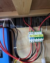
I ended up with the Sun1000 GTIL2 V7.1 22-65v as it has the limiter function as i am not allowed to feed into the grid (rental house, cannot install something permanently). I got 3 x 415w Panel here in Japan (a nightmare i can tell you to find a shop with normal prices) . Each has am Vmp of 42V and an Imp of 9.84A. Cable length 6m from each panel/ AWG10) to an 16A DC circuit breaker for each Panel . Then from that 3 breakers , 3x AWG10 from the breakers to plus of the SUN 1000 input. Same way for the negative site cables from the breakers to the SUN 1000. If i measure now the Amps between the input terminals of the SUN 10000, i only get around 1,5A . Same if i measure each panel on the breaker of even directly on the short cables of the panels.
Why so low AMPS even its a sunny day at nearly noon (from each panel). If i measure 1,5A on each panel, why not 4,5Amps on the input terminals of the SUN 1000.
Sorry, maybe a stupid question... just a mechanical engineer asking here ;-).
Also, i guess due to that, the SUN does not produce much Wattage ~250-300w most of the time (not enough as i can see on the display that i still draw 80-150w from the grid) and sometimes i see 700+w if i run a power hungry item in the house.
P.s. Panels have around 45V output if measured with a multimeter.
Need some advice if i see it wrong and everything is ok or not, please.
i just recently got into the Solar thing, to reduce my monthly power cost. As i am sitting in Japan where they have 100v only i was limited by the choice of inverters.
I ended up with the Sun1000 GTIL2 V7.1 22-65v as it has the limiter function as i am not allowed to feed into the grid (rental house, cannot install something permanently). I got 3 x 415w Panel here in Japan (a nightmare i can tell you to find a shop with normal prices) . Each has am Vmp of 42V and an Imp of 9.84A. Cable length 6m from each panel/ AWG10) to an 16A DC circuit breaker for each Panel . Then from that 3 breakers , 3x AWG10 from the breakers to plus of the SUN 1000 input. Same way for the negative site cables from the breakers to the SUN 1000. If i measure now the Amps between the input terminals of the SUN 10000, i only get around 1,5A . Same if i measure each panel on the breaker of even directly on the short cables of the panels.
Why so low AMPS even its a sunny day at nearly noon (from each panel). If i measure 1,5A on each panel, why not 4,5Amps on the input terminals of the SUN 1000.
Sorry, maybe a stupid question... just a mechanical engineer asking here ;-).
Also, i guess due to that, the SUN does not produce much Wattage ~250-300w most of the time (not enough as i can see on the display that i still draw 80-150w from the grid) and sometimes i see 700+w if i run a power hungry item in the house.
P.s. Panels have around 45V output if measured with a multimeter.
Need some advice if i see it wrong and everything is ok or not, please.
")