I think the input breakers should be same rating as pass through relay's rating in inverter. For Sunny Island that is 60A (actually 56A on inverter's spec's ), dual breaker for two series connected 240/120vac inverters.
Except, SI can pass 56A continuously. It is actually a 3p relay rated 30A. At first I thought 3 poles in parallel, but maybe one used for another purpose and 2x 30A rated contacts in parallel, derated slightly to 56A.
A 60A breaker shouldn't be used for 56A continuous, at least not a thermal breaker. Nor a fuse. Maybe a magnetic-hydraulic breaker.
Sunny Island will limit input current to 56A, so I'm not worried about over-current through relay under normal conditions. If there is a fault, 70A breaker would trip. I happen to have 63A breaker on input because I used DIN not yet another breaker panel to connect 2-pole switch to 2x 2-pole breakers to 4x SI.
SI manual says max 70A breaker on input, so that is kosher.
The SI manual says 56A max on the output. I used 70A initially, now 63A. I used 6 awg, which is good for 70A under moderate temperature conditions. 4 awg is better, can handle 70A in hotter conditions. Not that 70A will flow, but 70A fuse OK with proper NEC derating of wire ampacity.
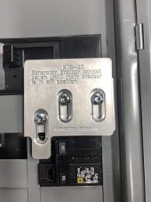
I am just going to use something like the pic below, which seems to be accomplishing the same thing you did with splicing 2 wires into one.
I've used a 2-hole version on main lugs of a sub-panel. That let me daisy chain to another panel.
I have to have the disconnect on the outside of the house near the mains coming from the power company. I have the solar disconnect and the battery disconnect - battery disconnect is the input from the inverters to the secondary loads panel.
So you have AC2 connected to grid. Isn't that where utility wanted disconnect?
Maybe you have Sunny Boys or other GT PV on AC2, so disconnect there accomplishes the same.
SI is also a UL-1741 inverter and can backfeed the grid under some conditions (DC coupled charging which raises battery voltage above SI's setpoint.) One more reason to have a disconnect between SI and main panel.
You haven't mentioned PV. Or if your SI system is just a battery UPS with no PV.
Especially if only AC coupled PV and no DC coupled PV, I would want to see a load-shed relay. That avoids running the battery down and having to do a black start.