Stay on 7.302 for the Islands. Some roll back to it because the Lith update forces you on to a active BMS to talk to the Island. The battery profiles set by them limit high and low settings when picking battery type. Ive never played with the TL line.


You are using an out of date browser. It may not display this or other websites correctly.
You should upgrade or use an alternative browser.
You should upgrade or use an alternative browser.
Sunny island 6048
- Thread starter maxx123
- Start date
Hedges
I See Electromagnetic Fields!
- Joined
- Mar 28, 2020
- Messages
- 20,699
Stay on 7.302 for the Islands. Some roll back to it because the Lith update forces you on to a active BMS to talk to the Island. The battery profiles set by them limit high and low settings when picking battery type. Ive never played with the TL line.
Ever play with SWR-2500U?
I can't get mine to respond to frequency shift. Have a couple different revisions of them and some updated V8.97 ROMS.
I tried to set grid voltage and frequency wide to manually implement Island mode.
Based on one document I set Vac-min to 50% of nominal and it lit the red LED. Codes indicated disagreement between voltage measurement from BFR and SRR. Corrected voltage. The command to reset error didn't do so, just set ground fault. Power cycle with fuse out fixed ground fault, but error remains and inverter isn't usable.
Hedges
I See Electromagnetic Fields!
- Joined
- Mar 28, 2020
- Messages
- 20,699
On the TL and Sunny Islands, Have you tried putting a large load on when disconnected from grid, eat up some of the solar watch how it behaves? anything 240v 10+ amps. or maybe unplug one of the strings?
Yes - one has three strings 2x Sharp 2kW each and 1x Astropower 2.8kW (STC)
I used an oil filled radiator 600/900/1500W.
Battery partially drained, SI would charge with whatever PV was available. As voltage rose and charge should taper off, SI would raise frequency from 60 Hz to 65 Hz over several seconds, causing SB to drop off around 64.8 Hz and come back on around 63 Hz.
With some PV strings disconnected so load was matched it would just hover along and stay on line.
All that was with default "UL1741" and backup "In all phases".
With "Island" it works beautifully. I could watch current vary with frequency as I switched load wattage.
I don't have a clamp ammeter yet, so that was with one string (2kW) connected to that inverter and the 10A setting of a DMM; it showed about 5.5A coming from Sunny Boy.
I did that test with and without another inverter producing several kW. This simply moved the frequency between about 61.8 and 61.95 Hz.
I want to get a couple clamp AC (maybe AC/DC) probes. Have to decide how much money to spend and what bandwidth, to use on a scope as well studying switching supplies. Two probes is so I can examine current balance. Looks to me like Square-D QO270 breakers were the cause of imbalanced current between paralleled SI. One leg had 0.5 to 0.6V drop at about 10A. One time I saw 1.2 kW on one slave and 0.5 kW on another. I've taken the wires out of the breakers and landed all four SI on two lugs in the load center. Now I see about 0.006V drop from wire to load center bus, and all four SI show about 1.9 to 2.0 kW (sun came out.)
I just measured a QO breaker 4-wire and got 0.040 ohms. Measured a Schneider 63A supplementary breaker and got 0.006 ohms. Maybe I'll use those on the Sunny Boy side of Sunny Island, as I have done already on the grid side.
What I haven't tried yet is large load and large PV production (like 10 kW each), fully charged battery, and switching load on and off.
That's where I wouldn't be surprised if voltage rose until SB disconnected, during the couple of seconds it takes to shift frequency.
Maybe then Solar Tech's suggestion of tight frequency band will help.
Hedges
I See Electromagnetic Fields!
- Joined
- Mar 28, 2020
- Messages
- 20,699
Kip are you doing a single 120v or dual inverter for 240v? I guess it does not matter but I suggest you buy a 240v panel such as this to feed from your SMA. Basic 240v panel. Even if your doing 120v you can use the cheap 240v home panels.
Rather than that "Homeline" model panel with aluminum bus, I prefer "QO" with copper bus:
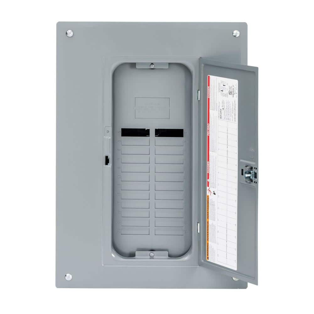
Square D QO 125 Amp 24-Space 34-Circuit Indoor Main Lug Plug-On Neutral Load Center with Cover, Ground Bar QO124L125PGC
The Square D QO 125 Amp Main Lugs Only 24-Space 24-Circuit Convertible Indoor Plug-on Neutral Load Center for Plug-on Neutral breakers is UL listed for residential, commercial and industrial power distribution.
www.homedepot.com
The QO series has copper bus for 125A and higher panels (but aluminum for 100A and lower). They work only with QO breakers, while Homeline fits many brands.
Tinned aluminum does get used extensively, including screw terminals, but I use copper wherever I can. Aluminum develops non-conductive oxide and if there's poor contact it will metal-migrate. Copper behaves much better.
Hedges
I See Electromagnetic Fields!
- Joined
- Mar 28, 2020
- Messages
- 20,699
Battery partially drained, SI would charge with whatever PV was available. As voltage rose and charge should taper off, SI would raise frequency from 60 Hz to 65 Hz over several seconds, causing SB to drop off around 64.8 Hz and come back on around 63 Hz.
With some PV strings disconnected so load was matched it would just hover along and stay on line.
All that was with default "UL1741" and backup "In all phases".
With "Island" it works beautifully. I could watch current vary with frequency as I switched load wattage.
Update on "backup" performance of Sunny Boy, I started a new thread:

Sunny Boy frequency-shift regulation of power output - which models work per spec?
I'd like to hear from you guys as to your experience with various model SMA Sunny Boy on Sunny Island systems. I'm not seeing them respond properly to frequency shift in "Backup" (default = UL1741 & backup = On All Phases or On, depending on model and interface.) I'm only getting it to work in...
 diysolarforum.com
Hi Picasso,Stay on 7.302 for the Islands. Some roll back to it because the Lith update forces you on to a active BMS to talk to the Island. The battery profiles set by them limit high and low settings when picking battery type. Ive never played with the TL line.
Would you share the battery setting on the SI when using lifepo4 with a bms without CanBus.
My SMA use is with Leaf cells, NMC. What cells (brand) size do you plan to use?
MurphyGuy
It just needs a bigger hammer
- Joined
- May 20, 2020
- Messages
- 4,129
2x Sunny Islands running on a Chevy Bolt 25kw Lithium battery bank. 10.7kw of solar array with 2x Sunny Boy SB6.0-US40 inverters. Frequency Shift Power control works amazingly well. We do shut down one of the Sunny Boy inverters when the bats are near full and its sunny out.
Grid Guard code is used to flip them into Island Mode when we go off-grid.. takes about 30 seconds.
System is completely isolated when not in use. We use a 6ga patch cord to connect to the house's main breaker box through an interlocked breaker to prevent the grid from ever being connected at the same time.
REC BMS controls all Sunny Island charging.
AC Grid and/or generator charging is through a separate cord. Its a 14s8p pack at 480ah of capacity. We usually keep it stored at around 3.6 volts per cell for longevity.
Just thought you all might enjoy the pics.
Attachments
daklein
New Member
- Joined
- May 8, 2020
- Messages
- 190
I set up a SI based system this year, made out of a DC Solar trailer. Here are some pictures of the system. AC coupled Enphase micro inverters, and some DC CC panels.
A question I have, for anyone with a grid tied or backup system that's integrated with your house, either wired in or plug in as needed: How do you have the neutral - ground bonding set up? The house has the neutral and ground bonded at the service entrance. If you are running the Sunny Islands only off grid not connected to the house, you would probably have the neutral and ground bonded near the SIs. A system is not supposed to have more than one path between N & G, and typically would be located at the main source of power, ie the service entrance or the SIs.
In my case, the SIs are in the garage about 120 feet from the main electric service at opposite end of the house. Once I started backfeeding the house panels, I attempted to use only the N-G bond at the service entrance, thinking that's the correct way. This created some voltage transients or spikes, and took out a couple items in the house: the fridge fan MOV & fuse, a kitchen clock radio, several internet device wall warts (Daddy broke the internet).
That event may have been a combination of things: 1) I've found that the freezers in basement, and likely the fridge, return some current on ground during compressor startup. Doesn't seem right, but from what I read, that may be common. 2) That first time, I was using a relative light wire to feed about 60 from the SIs back to the main panel in basement, a #12 4 wire cable & 20a breakers on each end. 3) A couple other circuits in the house did have faults from neutral to ground, typically not an issue and you'd never notice until trying to add a GFCI, but I checked carefully and fixed a couple as I moved circuits to the new basement critical loads panel. After fixing those faults, I typically did not see current returning on ground to the SIs any longer. Still do see it when the freezers start up though.
I put the N-G bond back at the SIs AC1 distribution panel. Everything worked fine, even with just the skinny #12 and managing loads to not trip the 20a. I then properly redid the basement panels, and have AC1 & AC2 linked with 50a breakers and #6 copper. The L1 & L2 for most all the house are fed by the SIs, a couple items L1 & L2 still on the utility in the basement grid panel, N & G are all connected together from service entrance through all the panels. If there's not quite enough sun, the SIs are set to connect on AC2 to charge if SOC is lower.
Everything is effectively done, and I think it should work with only the N-G at the service entrance. I'm gunshy to remove the N-G bond at the SIs, for fear of another Daddy playing lightning in the garage, resulting in Daddy fixing all the appliances again.
I'm concerned that without the (incorrect) N-G bond at the SIs, the transient ground current from the freezers will have to go all the way out to the service N-G bond, then on N from there all the way back to the garage.
Hedges
I See Electromagnetic Fields!
- Joined
- Mar 28, 2020
- Messages
- 20,699
My neutral/ground connection is only at the meter/main breaker box.
I have a breaker panel next to that, also visible blade disconnect for solar. Circuits from that panel go to a couple buildings.
About 40' away are my Sunny Islands (2S2P), connected with four 6 awg hot wires. From there, output if SI goes 20' with four more hot wires to PV panel. Neutral and ground go from the first panel to the PV panel (and earlier grid tie only setup), and neutral and ground go from PV panel to SI.
I haven't had any issues like you describe.
Most things wouldn't be harmed by voltage between GND and neutral.
What does harm things is if neutral goes open circuit, so 240V goes to one wall wart or clock radio in series with a refrigerator. I learned about that as a kid, opening a live circuit to tap off a branch for my workbench.
Do you switch or loop back neutral in any way? No chance you connected utility hot to SI neutral and vice versa, is there?
My neutral is always connected, and I happened to branch off neutral to SI rather than feeding neutral through it as one might normally do when hooking up AC1 & AC2.
"backfeeding the house panels, I attempted to use only the N-G bond at the service entrance"
I do have a backfeeding arrangement (interlocked breakers in first panel) and that is just two hots.
I even have a fridge/freezer on a GFCI (spare on porch). I don't think they should have ground current.
Clothes dryer I managed to rewire so it could be on GFCI.
2x Sunny Islands running on a Chevy Bolt 25kw Lithium battery bank. 10.7kw of solar array with 2x Sunny Boy SB6.0-US40 inverters. Frequency Shift Power control works amazingly well. We do shut down one of the Sunny Boy inverters when the bats are near full and its sunny out.
Grid Guard code is used to flip them into Island Mode when we go off-grid.. takes about 30 seconds.
System is completely isolated when not in use. We use a 6ga patch cord to connect to the house's main breaker box through an interlocked breaker to prevent the grid from ever being connected at the same time.
REC BMS controls all Sunny Island charging.
AC Grid and/or generator charging is through a separate cord. Its a 14s8p pack at 480ah of capacity. We usually keep it stored at around 3.6 volts per cell for longevity.
Just thought you all might enjoy the pics.
Nice system.
What is the model number of the RS485 in the Sunny Boys
Hedges
I See Electromagnetic Fields!
- Joined
- Mar 28, 2020
- Messages
- 20,699
What is the model number of the RS485 in the Sunny Boys
His SB6.0-US40 (also latest US41) models don't have an RS485 interface. That would be why SMA document SB-OffGrid-TI-US-en-21 says they are usable in a Sunny Island off-grid but not grid-backup system, and why he manually reprograms to island (off-grid) mode.
Those Sunny Boy have a "Speedwire" or Ethernet interface compatible with Sunny Boy Storage (400V battery) inverter.
When I asked SMA what could be used with Sunny Island, they said that the newer Sunny Boy (also some older models which don't correctly implement backup mode) could be used in "island" mode behind Sunny Island for grid backup, because Sunny Island provides the UL 1741 anti-islanding function.
That differs from what SB-OffGrid-TI-US-en-21 says:
"PV inverters without backup operation
For PV inverters without backup operation, the country data set must be set to the locally typical value for grid-tie
PV systems as per UL1741. The PV inverter is then configured for operation on the utility grid. In the event of a utility
grid failure, the Sunny Island is unable to derate the PV inverters by means of Frequency-Shift Power Control (FSPC).
If there is an excessive supply of energy, the PV inverters will switch off."
I suggest asking SMA directly, and saving their email reply if it tells you to do something different from what they've published.
Hedges
I See Electromagnetic Fields!
- Joined
- Mar 28, 2020
- Messages
- 20,699
I'm concerned that without the (incorrect) N-G bond at the SIs, the transient ground current from the freezers will have to go all the way out to the service N-G bond, then on N from there all the way back to the garage.
If you traced out where current flows in hot and neutral wires (and maybe ground in your case, since you think freezer puts start-up current through ground), does the current ever form a loop with large area between wires, e.g. neutral or ground routing several feet from each other or from hot wires, rather than being bundled together? Does any of it go through a steel conduit that doesn't contain all the others?
Loop area creates inductance, and wrapping ferrous metal around a conductor (between the conductor and return path that completes the loop) creates inductance. A wire that goes a way a distance by itself but then routes current back right next to itself does not do that. (for instance, using romex 2 wire + ground to to to a switch.) Current through a wire creates magnetic field, but equal and opposite current in an adjacent wire cancels it.
If your wiring creates any inductance instead of having only low-impedance paths (current out and back adjacent to each other), then you would get spikes and dips in voltage. If so, reduce/eliminate loop area by using wires that are together, not routed separately.
Wire resistance would still cause a dip in voltage during motor start-up, but not a spike when start-up ends.

image from:
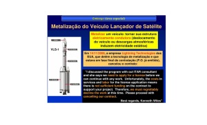
6 – Terceira possível causa do acidente ocorrido com o VLS-1 V03, em 22 de agosto de 2003, em Alcântara, Maranhão.
dallapiazza@gmail.com O slide abaixo aborda uma questão que é um fator técnico no acidente com o VLS-1 V03: Fonte: (GOMES, 2008) Se a superfície da estrutura do VLS-1 V03 não possuía metalização, e…
 dallapiazza.wordpress.com
MurphyGuy
It just needs a bigger hammer
- Joined
- May 20, 2020
- Messages
- 4,129
There is no direct communication between the Sunny Islands and the Sunny Boy inverters, nor do you need any.Nice system.
What is the model number of the RS485 in the Sunny Boys
There's basically 3 levels of control the Sunny Islands can use, all of them work, some work "smoother", for lack of a better term..
Type 1: On/Off control. This allows the Sunny Islands to be used with pretty much any grid tied inverter. When the batteries are charged, and the loads are minimal, the SI's will raise grid frequency. If the grid tied inverter can't do FSPC (Frequency Shift Power Control) than they will just trip out as they would anytime the grid went out of spec.
Type 2: Freq Shifting. This is what I have. If you're grid tied inverters are capable of FSPC, then as the SI's raise the grid frequency past 61hz, the grid tied inverter will throttle down its output to match the inverse of the freq. So at 61.1hz, my inverters will only put out 90% of their max power.. at 61.5hz, they only put out 50%, at 61.9hz, they only put out 10%, and at 62hz, they trip and shut down. This works VERY smoothly, but you have to change inverter settings each time I go off-grid. Takes about 30 seconds with a browser.
Type 3: RS485: I don't have this, but I believe its the same as Type 2 with the exception being you don't have to make any changes to the inverter settings.. Not completely sure of that.
There's one other aspect I didn't mention and that is that I only need to change my Sunny Boy inverter settings because of the way I have my system wired. If the Sunny Islands were being used full time with a critical loads sub panel, you could leave your grid tied inverter in Island Mode all the time.. The SI's would then act as the UL1741 shut down protection if the grid failed. But instead of shutting down the GT inverter(s), they just open the pass-through relay to isolate the mini-grid (your house) and continue as if nothing ever happened.
The system works incredibly well.. I was simultaneously scared and in awe the first time I had it running on its own.. its just a sight to see.. and a bit strange for someone used to seeing their GT inverter become a paperweight when a storm knocks out power.
You can see the big black round receptacle on the box below the Sunny Island, that's where I plug the patch cord into.. There's another one on the back side of that box, with a different kind of plug for grid or generator charging. I set the SI to draw about 10amps when grid charging.. that gives me about 2.4kw per hour of charge. I let it run like that for an hour and it only brought the batteries up 0.5 volts.. LOL. Good for storage levels to be at around 3.6 per cell. Anything above that and those nasty parasitic reactions start degrading your cells even though they're just sitting there.

MurphyGuy
It just needs a bigger hammer
- Joined
- May 20, 2020
- Messages
- 4,129
His SB6.0-US40 (also latest US41) models don't have an RS485 interface. That would be why SMA document SB-OffGrid-TI-US-en-21 says they are usable in a Sunny Island off-grid but not grid-backup system, and why he manually reprograms to island (off-grid) mode.
Those Sunny Boy have a "Speedwire" or Ethernet interface compatible with Sunny Boy Storage (400V battery) inverter.
When I asked SMA what could be used with Sunny Island, they said that the newer Sunny Boy (also some older models which don't correctly implement backup mode) could be used in "island" mode behind Sunny Island for grid backup, because Sunny Island provides the UL 1741 anti-islanding function.
That differs from what SB-OffGrid-TI-US-en-21 says:
"PV inverters without backup operation
For PV inverters without backup operation, the country data set must be set to the locally typical value for grid-tie
PV systems as per UL1741. The PV inverter is then configured for operation on the utility grid. In the event of a utility
grid failure, the Sunny Island is unable to derate the PV inverters by means of Frequency-Shift Power Control (FSPC).
If there is an excessive supply of energy, the PV inverters will switch off."
I suggest asking SMA directly, and saving their email reply if it tells you to do something different from what they've published.
Ya.. what he just said is very accurate.
If your GT inverters are connected to a critical loads sub panel, which is then connected to the AC1 (Loads) side of the Sunny Island, you can set for Island Mode and leave it there full time.
The problem I have with such a setup is that if a lightening strike hits, it could then wipe out the expensive inverters. So with that being a concern, I keep mine totally isolated and just connect a 4 wire patch cord when using them. Its not any different than connecting a portable generator, only that they can make the GT inverters work when connected.
Hedges
I See Electromagnetic Fields!
- Joined
- Mar 28, 2020
- Messages
- 20,699
Ya.. what he just said is very accurate.
If your GT inverters are connected to a critical loads sub panel, which is then connected to the AC1 (Loads) side of the Sunny Island, you can set for Island Mode and leave it there full time.
The problem I have with such a setup is that if a lightening strike hits, it could then wipe out the expensive inverters. So with that being a concern, I keep mine totally isolated and just connect a 4 wire patch cord when using them. Its not any different than connecting a portable generator, only that they can make the GT inverters work when connected.
I figure I'm less likely to get lightning damage, due to location and because utility feed is underground from an underground transformer. Half a block away the (12kV?) input goes up a pole and is above ground beyond that. I'm in the process of installing a hefty TVS system since discovering that my Delta lightning arrestors happily let 5000 Vrms go by; they obviously aren't the "Varistor" claimed on vendors site. Rumor has it they just contain sand; that is the "silicon oxide" part of "silicon oxide varistor"
I will also add varistors on the DC side. There are small ones on input of some of my Sunny Boys but SMA recommends more. I also have the Delta sand-filled bottles there.
I have manual transfer switches in a few places, so I can put the house direct on grid if Sunny Island is down. Was going to do that with the Sunny Boys as well, interrupting RS-485 so it would know Sunny Island was no longer performing UL 1741 and Sunny Boy should resume doing that. But because 10000TLUS doesn't respond correctly to RS-485 I didn't, it is only on Sunny Island's output.
It isn't quite there yet, but I want to set up UPS operation for the house (keep internet going for work at home), also my lab. Sunny Island will detect brownout and protect things from damage (which I've seen before.) I need to set up load shed of heating/cooling loads at about 10% DoD so they don't drain the small battery.
Similar threads
- Replies
- 8
- Views
- 457
- Replies
- 39
- Views
- 747
- Replies
- 3
- Views
- 293
- Replies
- 0
- Views
- 417