diy solar

diy solar

Supercapacitor Pre-Charge/Discharge DIY Circuit

JBertok

Network Engineer
Joined
Jul 24, 2022
Messages
140
Location
Riverside, CA
Recently a bank of 24 Nesscap 3500F Supercapacitors was added to my system to assist with DC ripple and surge loads. Although a big investment, their performance and the preservation of battery longevity they provide is worth it, in my opinion. These capacitors will easily pass 1500 Amps and would look like a short circuit if just connected to the DC bus - resulting in welded breakers, likely damage to the inverter(s), fire, death, etc. These things can make rail guns - they are no joke! A pre-charge resistor is mandatory. I thought I would share what I did for those considering this upgrade.

For 48V nominal Systems:
Flooded Lead Acid - (24) 2.7V Super capacitors in series required for support up to 64.8V
Lithium Iron Phosphate - (22) 2.7V Super Capacitors in series required for support up to 59.4V

A 5 ohm 500 watt resistor when connected at a battery voltage of 52V will take 10.4A and about 540W. The wattage and amperage begins to fall off as the capacitor bank voltage begins to rise, and the wattage passing through the resistor will be a product of the voltage difference between the DC bus and the capacitor bank. At 50V delta it's 500 watts for a 4 ohm resistance; I consider the momentary over-rating of the 500W resistor acceptable. The resistor does get quite warm at first but the power running through it tapers off logarithmically.

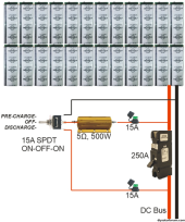
In practice, the circuit below takes over 3 hours to pre-charge a bank of twenty-four 3500F capacitors up to the DC bus voltage. The same is true for discharge, and the voltage of the capacitor bank should be monitored before closing the big 250A breaker to bring the capacitors online. (I have a panel-mount DC Volt Meter to monitor Capacitor Bank voltage. Anything will do.)
1694823596486.png
 
Last edited:
Dangit, now you got me wanting super caps again. There is just something about them I really like, even though I know it's generally best to just add more lifepo4.
 
My system uses the solar charger to get the supercaps to the same voltage as the batteries before it connects.
 
My system uses the solar charger to get the supercaps to the same voltage as the batteries before it connects.
How are you doing that? Don't many types of chargers indicate to not connect them up to things with capacitors? If it's ok to use a charger, a small 48v charger or a dc to dc converter would be a nice way to do it.
 
Something that sophisticated and you use a resistor for charging, wasting half your power.
 
I should explain why something like this is necessary.

Capacitors, in general, have enormous capacity to receive and release current. Their internal resistance is very low throughout their entire voltage range. The reason Lithium chemistry battery pack often have a "pre-charge resistor" is so that the capacitors in the inverter can be safely brought up to voltage without tripping the overcurrent protection in the battery breaker. Lithium batteries have a low internal resistance and will send too many amps into an empty capacitor bank when connected them. To be clear, the input capacitor bank inside a good inverter, is close to ONE HUNDRED THOUSAND TIMES less powerful than a bank of these supercapacitors. At the scale of super capacitors, this very low resistance is so capable and eager to take massive current that you cannot just connect a bank of them to a DC bus when they are discharged - it will absolutely short-circuit the DC bus as it tries to take thousands of amps. I cannot underscore enough how dangerously powerful these things are which is why caution and diligence is so critical with handling them.

There are 2 problems a charge/discharge resistor circuit solves:
- Preparing the capacitor bank to be safely coupled to the DC bus.
- Emptying the capacitor bank so that system maintenance can be performed safely.

There are 3 modes of operation this arrangement provides:
- NORMAL: The DC disconnect breaker is closed and active. The charge/discharge circuit and resistor are off and all dormant.
- PRE-CHARGE: The DC disconnect breaker is open. The switch is in the charge position and current flows through the resistor from the positive side of the DC bus to pre-charge the capacitor.
- DISCHARGE: The DC disconnect breaker is open. The switch is in the discharge position and current flows from the capacitor positive through the resistor to the negative.

Returning to a NORMAL operating state is accomplished by closing the DC disconnect breaker, but that should not be done until the voltage of the DC bus and the supercapacitor bank are within 2 volts of each other. This protects the DC disconnect breaker contacts from being welded together.

Why discharge the capacitor bank before maintenance or removal? The amount of current it can instantly deliver is sufficient to weld a crescent wrench across the terminals, and then liquify it an instant later. Shorting also will damage the capacitor protection modules and/or even the internals of the capacitors themselves, which could trigger high-pressure venting. What split-second option do you have to deal with something glowing white-hot that's dripping molten metal through and setting fire to whatever is beneath them turning your massive investment into slag? There is no forgiveness if anything makes accidental contact; you get a disastrous runaway meltdown.

I hope this helps clarify the point of this system.
 
Last edited:
Something that sophisticated and you use a resistor for charging, wasting half your power.
I've seen some of the impressively crazy things you do, but can't for the life of me figure out an alternative solution that isn't overly complex, possibly involving PWM.
But in the end, how often are you precharging this capacitor bank? Maybe annually? Not to many Wh wasted there. Once precharged, the resistors is done a d not flowing current.
 
I might use this thing maybe 5 times in the rest of my life. I have no intention of needing to shut down the DC bus, but if I do need to disconnect the capacitors for any reason, I need to be able to do it safely. It doesn't need a PWM controller or any complexity, it just needs to be ready to work reliably when called upon.
One example I can think of is changing out the batteries. I don't want the DC bus hot while doing that, so total shutdown is implied.
 
How are you doing that? Don't many types of chargers indicate to not connect them up to things with capacitors? If it's ok to use a charger, a small 48v charger or a dc to dc converter would be a nice way to do it.
I haven’t had any issues. In typical operation the inverter will disconnect before a battery limit, but if there is a low cell fault the battery disconnects from the DC bus. (supercap / inverter / solar charger remain connected). The supercap will power the inverter until the inverter LVD.

At this point only the supercap and the solar charger are connected to the DC bus, and the supercap will be lower voltage than the battery.

As the solar charger charges the supercap to just above battery voltage the next day the BMS reconnects via an automatic precharge to the bus. There is a NH00 100amp fuse as backup protection.

When the voltage rises to useable level the inverter reconnects.
 
Something that sophisticated and you use a resistor for charging, wasting half your power.
I've used this resistor only one time for the initial pre-charge of the capacitor bank before coupling it to the main battery DC bus. I don't anticipate needing to use this again unless it becomes necessary to disconnect and discharge them, and then recharge again before reconnecting. Unless there is some problem, the capacitors will be connected at all times directly to the main battery DC bus, through a dedicated 250A breaker.

I like numbers, so here they are:
I paid $43.11 for the $28.95 5-Ohm 500 Watt resistor including tax and shipping (eBay).
At 52 Volts, a 5 Ohm resistor will pass 10.4 Amps, 540.8 Watts, across it to a dead short.
A Supercapacitor or a bank of them at 0 Volts is a dead short, for all intents and purposes.
Wattage across the resistor (and therefore pre-charge rate) tapers off logarithmically as capacitor bank voltage rises toward DC bus voltage.
The bank I have is constructed of (24) 3500 Farad 2.7 Volt Nesscap supercapacitors in series, for a total of 145.83 Farads.
Pre-charging 145.83 Farads of capacitance to 52 Volts takes 54.77 Watt/Hour, or 1.05 Amp/Hour.
Each Watt pre-charged into the capacitors through the resistor will dissipate an equivalent wattage as heat from the resistor's heatsink, so 109.54 Watts to fully pre-charge. Discharging from 52 Volts will also dissipate 54.77 Watt/Hour as heat through the resistor.

As infrequently as I anticipate having to use this circuit, it will cost me 109.54Wh each time for a full discharge and recharge.
POWER COST - If this power comes from the grid with a price (Tier 1) of $0.1102/kW * 94.1% inverter AC-DC efficiency =1.28¢ USD

I think about $50 in parts and less than two pennies in power are acceptable?
 
I haven’t had any issues. In typical operation the inverter will disconnect before a battery limit, but if there is a low cell fault the battery disconnects from the DC bus. (supercap / inverter / solar charger remain connected). The supercap will power the inverter until the inverter LVD.

At this point only the supercap and the solar charger are connected to the DC bus, and the supercap will be lower voltage than the battery.

As the solar charger charges the supercap to just above battery voltage the next day the BMS reconnects via an automatic precharge to the bus. There is a NH00 100amp fuse as backup protection.

When the voltage rises to useable level the inverter reconnects.

Oh ok. You are talking about once it's already connected and operating. How did you get the supercap charged up and into the mix in the first place?
 
Oh ok. You are talking about once it's already connected and operating. How did you get the supercap charged up and into the mix in the first place?
I charged it through a carbon pile resistor (automotive battery tester) from my LiFePO4 at 40A.
 
How long have you been hanging onto that bad boy?
I’m an auto electrician by trade - had that battery tester for decades, it will pass 500amps but needs cooling. 40A hardly makes it warm.

After I first commissioned this system, the battery would disconnect before the inverter low voltage disconnect, so there were a few times the system got “tested”, by running the DC bus with only the inverter / charger / and supercap. It’s been a few years since I raised the LVD on the inverter to prevent this happening but it didn’t cause any noticeable issues.
 
I wish I had a 12V battery tester like that, one of the few tools I actually don't have an example of. Something that big wouldn't have worked for me though, not at 52 Volts. A 500A 12V (6000W) battery CCA tester would be have 0.024 ohm of resistance and allow 2166A with 52V of delta between the DC bus and empty capacitor bank - and the caps would try to take it. 112,666 Watts. The batteries could never supply that, it would look like a dead short, but what's worse is that it would pull the whole system instantly into low-voltage-disconnect and trip all the battery breakers if you have LiFePO4. Hopefully nobody gets the idea to try using one of those without doing some math first!
 
I wish I had a 12V battery tester like that, one of the few tools I actually don't have an example of. Something that big wouldn't have worked for me though, not at 52 Volts. A 500A 12V (6000W) battery CCA tester would be have 0.024 ohm of resistance and allow 2166A with 52V of delta between the DC bus and empty capacitor bank - and the caps would try to take it. 112,666 Watts. The batteries could never supply that, it would look like a dead short, but what's worse is that it would pull the whole system instantly into low-voltage-disconnect and trip all the battery breakers if you have LiFePO4. Hopefully nobody gets the idea to try using one of those without doing some math first!
The carbon stack is gradually compressed to allow the desired current. You can allow 1amp only if that is what is desired.

When testing a car battery you start with the carbon stack opened, and compress it until the current reaches the batteries CCA rating while monitoring the voltage.

When using on a 48V LiFePO4 to supercap, i dialled it to 40A.

The only catch is with cheaper 12V only testers you need to disconnect the fans / gauges that are only rated for 12V batteries. (the carbon stack is fine to use).

Yes, if you fully compress the stack and then connect it you will pop fuses (or open FET’s). Please take a video if you try this!
 
Back
Top