There was a report on this forum, perhaps a search will find. I seem to remember the situation, with the batteries linked, was an inability to deliver full battery current . By removing the link the batteries behaved as expected.
Renogy have bizarre 'shelf' mode where the battery will shut down if no significant charge/discharge takes place, again this has been discussed on this forum.
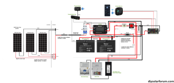
Hi, I put a new 200Ah Renogy bluetooth battery in an existing van. The van has a Victron DC/DC charger, and an Epever MPPT solar charger. Both the Victron and the Epever MPPT have been working, and I have also seen them working on the Renogy battery. Also the Renogy battery itself works fine, it...

diysolarforum.com
Another issue that sometimes appears on the forum, ,(applies to many low cost batteries), is that a high charge voltage, 14.4 volts, causes the battery BMS to shutdown the charge path , ( due to cell inbalance causing the BMS to enter protection mode). This may have undesired effects on the system voltage as the charger may be slow to respond. Renogy technical help suggested lowering the charge voltage, ( down as far as 13.8 volts if necessary), not all chargers have this option. It's not usually a serious issue and over time the battery becomes more balanced.