diy solar

diy solar

Testing a Cabin Set-Up :: Issue with Inaccurate Victron SmartShunt!

savagecabbage

New Member
Joined
Dec 20, 2022
Messages
9
Below is background info on my setup. Please see most recent thread post for Victron SmartShunt issue!!!

I recently purchased a small off-grid cabin setup and have been testing it this week. I'd appreciate any feedback on the controller settings and other considerations I may not be noticing.

Equipment: 900W solar, 80A EPEVER Solar Controller, Two 12V 200aH Ampere Time LiFePO4 batteries (in series), Giandel 4000W inverter

unnamed (4).jpg

Load: Only laptops and Starlink internet for now. At the cabin, it will be two 15A circuits, one for lighting and one for outlets. A small efficient fridge and the 30W internet is the only constant load.

Location: Northern Baja Mexico (tons of sun)

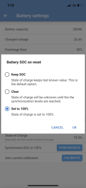
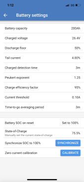
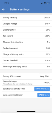
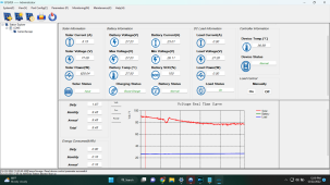
Here are the controller settings:

Screenshot (449).png

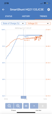
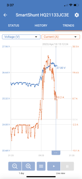
Here is the read-out during a charge from 26.0V (Boost Voltage) with almost a full day of sun, one earlier in the day (630W of solar at noon), one later (155W at 4pm):

Screenshot (446).png

Screenshot (447).png

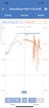
Here is the read-out soon after switching to Float Charge the next day (switch is at 28V):

Screenshot (448).png

Obviously the laptops and Starlink weren't enough to drain the batteries to see a full bulk cycle into float, so I disconnected the solar for a day to draw the batteries down a bit before recording these screenshots.

My main questions:

- How do my controller settings look for a safe charging cycle and long battery life?

- How does the controller sense SoC? When I drew down to 26V I was expecting the SoC to be around 30% but the controller read 85% at the beginning of the day, then quickly moved to near 100% well before boost voltage was reached (only a few hours into charging). Is it due to the controller not having a dedicated LiFePO4 setting and using voltage levels from lead-acid?

- Should I use a different circuit for lighting and go with a 12V system, or is the 10% in gains not worth the difficulty of lack of 12V lighting options?

Overall, I am happy with the bench testing of the system... if I need to expand capacity I'll probably just add two more batteries (2S2P), as I feel like the panels won't be the weak point of the system, it'll be night time capacity if anything.

Appreciate any feedback!
 

Attachments

  • Screenshot (446).png
    Screenshot (446).png
    492.7 KB · Views: 8
Last edited:
- How do my controller settings look for a safe charging cycle and long battery life?

Boost of 3.45V/cell with a 2 hour boost period generally gives a longer charge time, lower peak current and improved cycle life.

Float is good.

Do those Amperetime have cold temp charging protection?

- How does the controller sense SoC? When I drew down to 26V I was expecting the SoC to be around 30% but the controller read 85% at the beginning of the day, then quickly moved to near 100% well before boost voltage was reached (only a few hours into charging). Is it due to the controller not having a dedicated LiFePO4 setting and using voltage levels from lead-acid?

It doesn't. That number is based on voltage and has no meaning if there is any charge or discharge, and it's almost certaintly only slightly accurate for lead-acid after the system has been completely inactive (no charge or discharge) for 10+ hours.

You need a battery monitor for true SoC. Aili Shunt or Victron smartshunt are popular. If you spring for a BMV-712 battery monitor, you get an external display AND a control relay, i.e., you can open and close a relay based on voltage, SoC and temperature if you have the probe.

- Should I use a different circuit for lighting and go with a 12V system, or is the 10% in gains not worth the difficulty of lack of 12V lighting options?

Only if you need the additional capacity. I'm powering 2X RVs with "shore power." My 48VDC to 120/240VAC to 12DVC conversion is only about 75% efficient. Simply put, I don't care about it. It's not worth the time or expense. Plus, each RV has it's own 12V "backup" in case shore power goes down.

Overall, I am happy with the bench testing of the system... if I need to expand capacity I'll probably just add two more batteries (2S2P), as I feel like the panels won't be the weak point of the system, it'll be night time capacity if anything.

Didn't scrutinize it intensely, but it looked good overall. PV determines how much power you can use with a good day of sun. Battery determines how long you can go between charges.

Starlink is down to 30W? That's cool. IIRC, 1st gen is around 100W. If it ever comes available in my area, I might ditch the 20MBit DSL.

Estimating your fridge + starlink is about 1-1.2kWh/day. That's 4-5 days on battery, and you have way more than enough solar even in Winter (excluding weather).
 
Thanks for the informative reply here... @sunshine_eggo

I'll look into dropping the boost voltage a little and increasing the boost period. My settings were taken from notes I compiled from @mikefitz who seemed to be pretty knowledgeable and familiar with the EPEVER + lithium setup.

The ampere time batteries DO NOT have cold weather protection, so outside of an area that never sees below freezing temps, I certainly wouldn't recommend them.

Can someone explain how a dedicated battery monitor gives and accurate reading if the batteries are almost always charging or discharging? I have installed them on a couple vans and agree they seem accurate, just never knew exactly how they work.

Yes the new starlink rarily is pulling more than 30 watts at 120V which is really impressive. The system overall is pretty incredible, and because I live in Mexico I'm only paying $65/mo which is totally worth the service compared to alternatives here.
 
Thanks for the informative reply here... @sunshine_eggo

I'll look into dropping the boost voltage a little and increasing the boost period. My settings were taken from notes I compiled from @mikefitz who seemed to be pretty knowledgeable and familiar with the EPEVER + lithium setup.

Nothing wrong with the programmed levels. Mike is correct. You added "long battery life," so I modified it.

The ampere time batteries DO NOT have cold weather protection, so outside of an area that never sees below freezing temps, I certainly wouldn't recommend them.

Can someone explain how a dedicated battery monitor gives and accurate reading if the batteries are almost always charging or discharging? I have installed them on a couple vans and agree they seem accurate, just never knew exactly how they work.

Because you tell the battery monitor how big your battery is and what the "charged" criteria are, so it knows when to reset itself to 100%. The battery monitor literally counts the current in and out of the battery and reports SoC vs. programmed capacity, e.g., if you have a 100Ah battery and use 10A for 1h, you've used 10Ah. The unit would then report you have 90/100Ah remaining or 90%. If you then charge with 5A for one hour, it keeps track of this and reports 95% SoC. Provided you fully charge the battery at least a couple times a month, the monitor should stay pretty accurate - leaps and bounds more accurate than your controller.

Yes the new starlink rarily is pulling more than 30 watts at 120V which is really impressive. The system overall is pretty incredible, and because I live in Mexico I'm only paying $65/mo which is totally worth the service compared to alternatives here.

Nice. That's about what I pay for 20Mb DSL.
 
Because you tell the battery monitor how big your battery is and what the "charged" criteria are, so it knows when to reset itself to 100%. The battery monitor literally counts the current in and out of the battery and reports SoC vs. programmed capacity, e.g., if you have a 100Ah battery and use 10A for 1h, you've used 10Ah. The unit would then report you have 90/100Ah remaining or 90%. If you then charge with 5A for one hour, it keeps track of this and reports 95% SoC. Provided you fully charge the battery at least a couple times a month, the monitor should stay pretty accurate - leaps and bounds more accurate than your controller.

Absolutely clear now, thanks for that easy understanding... will be trying to find a decent WiFi version so I can check from afar!
 
Please let us know if you find one. I don't think any exist. There are bluetooth ones as well as "RF" ones that have a slightly longer range, but I've never seen a wifi one.

Any chance you could help with a recent issue??

I added a Victron Smart Shunt when I did the actual install of this equipment. After a full day of charging without any draw I set the calibration to 100% full on the shunt and have since monitored SOC rather than voltage.

Under normal conditions my usage has never been more than 99aH of a 200aH system. Then after three days of clouds I tripped low voltage alarms at 23.2V but the shunt was still reading 55% SOC!

How is this possible and what is going wrong here? Was the shunt not calibrated correctly or do I have larger undetected battery issues? If the shunt is accurate I should be over 26V! So how was I down at 23!?

The worst is when a smart piece of tech that you become completely reliant on suddenly betrays your trust ?
 
Dam
Any chance you could help with a recent issue??

I added a Victron Smart Shunt when I did the actual install of this equipment. After a full day of charging without any draw I set the calibration to 100% full on the shunt and have since monitored SOC rather than voltage.

Under normal conditions my usage has never been more than 99aH of a 200aH system. Then after three days of clouds I tripped low voltage alarms at 23.2V but the shunt was still reading 55% SOC!

How is this possible and what is going wrong here? Was the shunt not calibrated correctly or do I have larger undetected battery issues? If the shunt is accurate I should be over 26V! So how was I down at 23!?

The worst is when a smart piece of tech that you become completely reliant on suddenly betrays your trust ?
Damn. I think I found my problem. Somehow this was changed from default ?
 

Attachments

  • 05504BAA-39B4-4781-8D87-2DB532CF7A73.png
    05504BAA-39B4-4781-8D87-2DB532CF7A73.png
    385.1 KB · Views: 12
  • AFC9A6F4-DBAD-4903-933E-3055BFFB641A.png
    AFC9A6F4-DBAD-4903-933E-3055BFFB641A.png
    335.6 KB · Views: 12
Dam

Damn. I think I found my problem. Somehow this was changed from default ?

Can anyone help me understand “synchronization”… I’m looking for my smart shunt to just count the amps in and amps out from a state of full charge. How does synchronization play into this at all?
 
Synchronization is how your monitor 'recalibrates' to 100% SoC. The monitor measures current in and current out and keeps a running tally to estimate SoC. But those measurements aren't exact, and so the SoC can drift a little one way or the other (e.g., it may indicate 95%, when the real value is 100%). For the best indication, you need to periodically recalibrate the actual SoC, which is only known with any certainty at 100%.
Synchronization resets the SoC to 100%, and this can occur manually with the "Synchronize" button in your app, or automatically at the set of conditions you specify with the 'Charged Voltage', "Tail Current", and "Charged detection time" parameters. If voltage is >= "Charged Voltage" AND current <= "Tail current" for at least "Charged detection time", then SoC resets to 100%.
 
+1 to @LakeHouse.

If charging with solar, charged voltage needs to be set to 0.2V below absorption, not float. Solar can trigger false syncs if set to 0.2V below float, i.e., it will jump to 100% prematurely.

Tail current should be set to 6%.
peukert should be 1.05
efficiency should be 99%

"keep soc" is the best option. that is a recent addition.
I’m curious as to why 6% tail current … I switched to all your other setting and all is great ..I’m still at 2 % tail current on a 10k 24v system. It’s being charged by solar only at this point…that’s been easy in about in about 1 to 4 hours depending on discharge depth.
As I have no AC loads untill I finish installing the multiplus this week , I’m running tests at this point on moderate DC loads only….
The “ keep SOC “ is my setting and the current counting the 712 does so far from 100% to zero or a midpoint and the back up to 100 does is amazingly accurate.. it’s Very very close in its reporting …
Is 6% based on an anticipated current draw or average draw or or somthing else…i suspect as usual you know somthing I don’t ….
Thanks in advance…J.

LFP batteries are fully charged at 0.05C @3.65V/cell. That's a 5% tail current. In order to register a sync, the current needs to fall BELOW the tail current while at charged voltage. OP is charging to 3.60V/cell, so that's close enough.

If you're charging LFP to a lower voltage, you will need a lower tail current. 2% would not be unreasonable.

Loads shouldn't influence it because the shunt only measures the net flow in/out of the battery.
Ok …hmmmm …. I at 5his point charge to 28.84… that is 3.60… I will try it.. you’ve been right so far…i wont argue….when the multi is up and running it will be easier to cycle this whole thing than with 12&24 v devices… thanks…….J.
 
+1 to @LakeHouse.

If charging with solar, charged voltage needs to be set to 0.2V below absorption, not float. Solar can trigger false syncs if set to 0.2V below float, i.e., it will jump to 100% prematurely.

Tail current should be set to 6%.
peukert should be 1.05
efficiency should be 99%

"keep soc" is the best option. that is a recent addition.

Thanks for this! I'll finally set up the shunt correctly and see if voltage gets back in line with SOC here soon!
 
Last edited:
You can always enter a manual SoC to approximate it based on voltage rather than allow the false 100% to set the scale.
I guess I’m still confused. After setting my Charged voltage to 27.8V the shunt is synchronizing to 100% at far lower voltages.

Also, what’s with the wild swings of power on a sunny day with minimal clouds?
 

Attachments

  • 56E31F3D-49B4-4E3B-A8FD-CBBF2C560924.png
    56E31F3D-49B4-4E3B-A8FD-CBBF2C560924.png
    281.2 KB · Views: 4
  • E5B92FB4-96CF-4E5B-A3AF-6DA565CCB8D3.png
    E5B92FB4-96CF-4E5B-A3AF-6DA565CCB8D3.png
    347.3 KB · Views: 4
  • 0D28361B-1FD5-447D-8166-AB697035D053.png
    0D28361B-1FD5-447D-8166-AB697035D053.png
    336.1 KB · Views: 4
That's not a sync. That's counting, i.e., it's counting the Ah coming in and adjusting SoC. It was artificially high to start with, so it got to 100% before it should have.

A false sync would look like this:

1681510430208.png

an immediate jump.

The steady climb is indicative of counting.

The expectation is that tomorrow, you will show it hitting 100% far later than it did today.
 
Thanks @sunshine_eggo … the shunt has gotten more accurate each day now that the settings are correct.

One question now that I have all this data. On a perfectly sunny day like today, why is my controlled dropping into float around 27.15V and current amperage? I thought my settings would have the controller run to 28V at full amperage before cutting current and floating to 27V?
 

Attachments

  • C4E43BAC-B40B-4DE9-85DC-1BBCCB90FC49.png
    C4E43BAC-B40B-4DE9-85DC-1BBCCB90FC49.png
    359.9 KB · Views: 3
Thanks @sunshine_eggo … the shunt has gotten more accurate each day now that the settings are correct.

One question now that I have all this data. On a perfectly sunny day like today, why is my controlled dropping into float around 27.15V and current amperage? I thought my settings would have the controller run to 28V at full amperage before cutting current and floating to 27V?

Your shunt is measuring the open circuit voltage (OCV) of the battery. This voltage is the true voltage of the battery that's not influence by current flow in the measurement.

Your Epever voltage measurement is influenced by the current it's sending to the battery. There's resistance in the wires proportional to the current - more current, more resistance. This will cause the Epever to "see" a higher voltage than the shunt.

The Epever likely saw the absorption voltage and dropped to float.

There's also measurement error. Most equipment doesn't correlate 100%. Recommend you check the following with a voltmeter at night when there is no current from the MPPT:

1) Remove cover from Epever and record voltage at terminals for battery connection:
2) Record Epever's reported voltage:
3) Record voltage measurement AT battery terminals:
4) Record shunt reported voltage:

During high current production, it's worth comparing EPever reported voltage and shunt voltage.
 
Back
Top