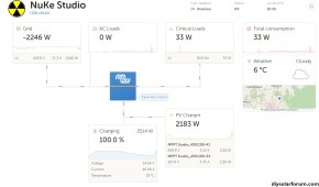
@sunshine_eggo Hooraah . . . Hit 100% SoC for over an hour today, and it brought up some interesting questions I'm sure you can explain to help my learning curve ? I appreciate your input and guidance so far.. ?
Glad to hear it.
Changes made & Questions >>
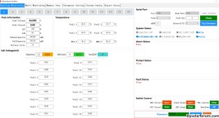
Over the last few sunny days I spent much time top balancing both parallel 48v packs (cabled one at a time to the system), but am still concerned about the voltage difference between them when in parallel. Is it completely normal to have around 0.5v difference at varying states of charge / discharge ? (I have incuded some BMS pics and Cell Delt Data)
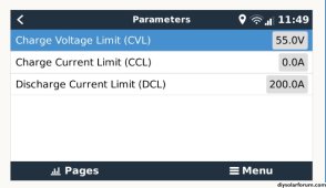
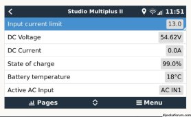
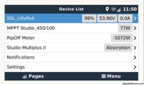
I see the MP is reporting 0.5V higher than the BMS. This is likely an error of some sort. Recommend you take the system offline briefly or pick a moment where currents are very low and record the voltage reported by all devices and then take a direct measurement at the appropriate terminals.
Inverter reports:
Inverter terminals measure:
MPPT reports:
MPPT terminals measure:
Battery X reports:
Battery X measures:
Worth noting that voltage disparities will scale with current. The Pylontech driver that your batteries use do NOT share the BMS voltage with the rest of the system. I have no idea why, but it's the stupidest thing ever.
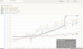
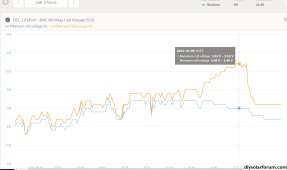
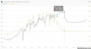
There appears to be a massive increase in the voltage disparity towards the end of the morning charge cycle about when the current curve intersects with the voltage curve as the current tappers off. (See graphs) Is this normal ?
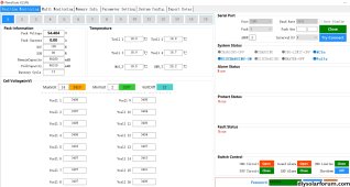
I also tried swapping the configurtion around making the slave > master and this is how I eventually achieved a great Cell Delta under 10mv/cell between all 32 cells. But the independant battery voltages still stray apart as above.
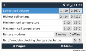
I'm seeing the max/min cell value diverge by about .12V at the end of the charge cycle. This is sign of mild to moderate cell imbalance. Note that voltage does not correlate to balance below 3.40V. Even imbalanced batteries will typically have very low voltage deviation below 3.40V.

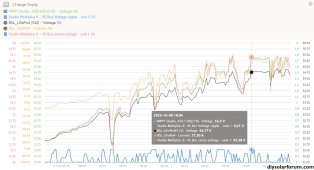
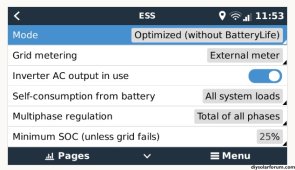
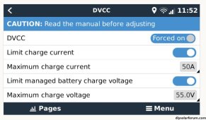
I kept all voltages set at 55.00v within the BMS, Cerbo CVL and DVCC but found I couldn't change the 'Fixed Solar Offset' of 0.4v as it appears hard coded into the Victron algorithm. (see charge graphs & pics) However, I'm still getting a voltage disparity at various times in the cycle where the CerboGX voltage is much higher than the actual BMS reported Battery Voltage, which is also higher than the voltage recorded within the BMS itself. (See BMS snapshots) Is this just due to cable losses ?
Each device takes its own measurement. The device's measurement will be influenced by any current is it supplying or drawing. AC charging will always show a higher battery voltage than the open circuit voltage measurement of the BMS.
That's why it's important to confirm all measurements under low and preferably 0A current.

At the indicated point, current is 0A, and the deviation between MPPT/MP and BMS is only about 0.1V. This is likely just an inherent error in voltage measurement that you can't avoid. As current increases, the voltage discrepancy increases. This is Ohms law in action, but you should confirm the measurements with a separate meter and check that all connections are of high quality and properly torqued.
Lastly, consult the MP manual. There is a V-sense pair of leads that's intended to act as a direct open circuit voltage measurement the MP uses instead of what it sees at the power leads influenced by current.
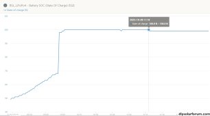
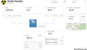
Finally, I noticed a very sudden SoC increase of 30% in a small time period..... I have no idea whatk that's about ? (see SoC graph)
The BMS counts current in and out. It's inexact. It has additional criteria to determine that it's fully charged regardless of what the count says. The BMS decided that regardless of where it was in its count, the cell voltage met the full charge criteria.

With improved balance and regular charging to 100%, these jumps should diminish and possibly disappear altogether unless you go for an extended period without full charges.
Thanks again for your help, and the custom widgets are very helpful ?
")