Thanks for sharing your brain cells Solar Guru dudes..... I appreciate it very much btw ??

Ok, so I've been testing all day with MUCH coffee after Night Shift. Here is my results thus far >>
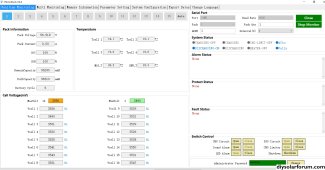
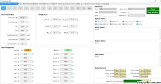
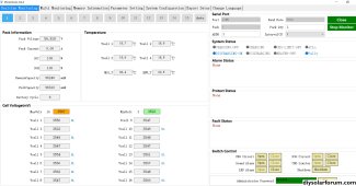
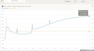
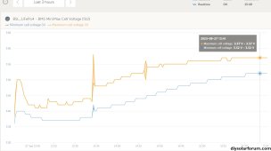
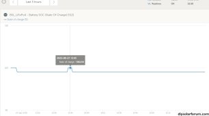
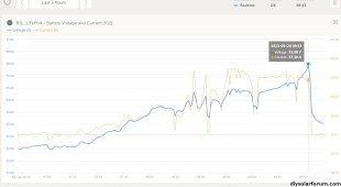
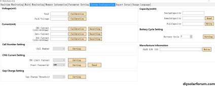
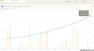
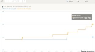
I've increased the BMS "Pack Full Charge Voltage" (as per parameter pic attached) to 56.3v and it is now charging and balancing slowly. The BMS recorded Voltage is increasing slowly above and slightly beyond 56.3v with the average Cell Delta slowly improving below 65mV (32 cells total)
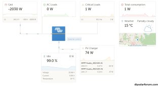
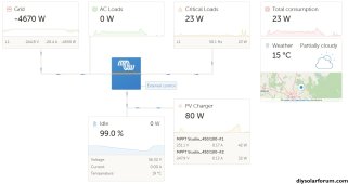
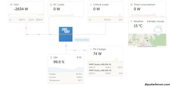
There is no battery current recorded in VRM, as I'd assume it's too low for VRM to record.
Using multimeter current is bouncing around between 0 - 1.3A balancing current. Voltage measured at terminals is bouncing around between the BMS voltage +/- 0.5v
Testing Conditions >>
I have selected 'keep battery charged' within the Victron ESS environment, which I believe apply's all available DC PV power to the battery, and no longer sharing this DC power with the loads on AC-In. This is just a precaution to avoid any undue interuption to the charge curve. (Plenty of sunshine here today
")
Stangely.... Whatever preset voltage I enter into the BMS.... It is always reflected into the Victron VRM and Cerbo etc as +0.5v ?? Is this normal ? Am I missing something ? Is there an automatic offset applied to these settings or some form of correction factor ? Mmmm ?
Thoughts>>
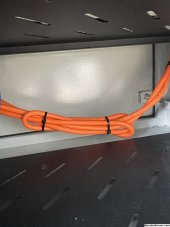
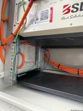
I'm now wondering if the length of my battery cables are causing a voltage disparity between the Battery and Multiplus/Cerbo that may be outside of an accepted range ? Could this be the cause of my system not reaching 100% even under perfect conditions ?
i.e. Battery Terminal Voltage is about 0.7v higher than Cerbo/VRM reported Voltage. Is this normal or too large a disparity ?
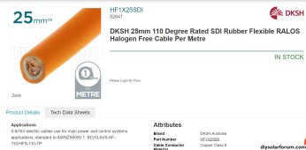
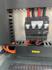
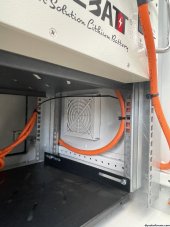
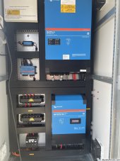
It should be noted that my battery cables appear way too long (see attached pics) and are both wired separately/individually from each battery back to a bus bar, that then feeds both the Multiplus Inverter and the MPPT Charger. The individual cable sizes are .25mm (4 AWG).
Could this influence my voltage this much ? Or am I barking up the wrong tree ? ?
I'm still somewhat confused as to how the 100% is actually decided, and by what hardware and under what conditions. Is it the BMS that reports 100% or the Cerbo ? I know some BMS's need a cdertain voltage to be maintaned for a certain time, along with a current threshold.... Then pop into 100% SoC. Some other BMS's even need a cell to hit the Over Voltage Protection value along with low current to report 100%. Any thoughts ?
Plz let me know what you guys think, and thanks again for your input. It's greatly appreciated ?