diy solar

diy solar

Thinking of adding a Victron Smart Battery Protect to my system

corn18

Village Idiot
Joined
Sep 9, 2021
Messages
676
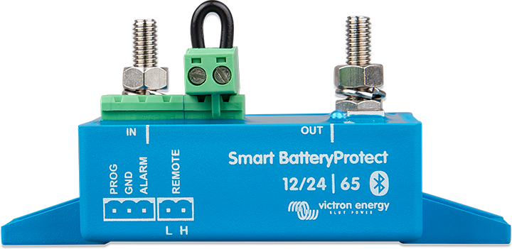
I am thinking about adding a Victron smart battery protect to my system. I would add it to the wire going to my DC distro panel. I won't add it to the line going to the front with the DC motor loads on it because that is also the line from the DC-DC charger from the truck. I could add a second Protect to those motor loads and run a separate wire for the DC-DC charger but I don't see the need. The motor loads won't drain the battery unless they are stuck. Appreciate your thoughts.

Now:

DC wiring 290RL rev 1.jpg

With protect:

DC wiring 290RL rev 1 protect.jpg
 
I have a Battery Protect in front of my 24V and 12V fuse boxes. It's there to ensure my DC loads get disconnected before the BMS is forced to do its job. As for your motors, presumably the only time the motors are turned on is when you are there doing so, therefore if they get stuck you are there to disconnect them before they drain the battery.

Unrelated but there's no real need for the Digital Multi Control for your inverter since the Cerbo provides the ability to see those same status lights, turn the inverter on/off (or put it in inverter-only or charge-only mode), and set the current limit.
I ordered the DMC with the inverter and just decided to keep it. Makes it super easy to do those functions.
 
I have the Victron Smart Battery Battery Protect (65 amp) ready to be installed in my RV. It will be used on the circuit going to the 12 volt main distribution panel. Other than having it on hand, I haven't done anything with it. I am working on a bus bar to go between the common bus bar and the Battery Protect (instead of a cable).

I'm trying to figure out where the fuse goes. Before or after the Battery Protect? You have yours before.
The Victron manual shows the fuse before. I think I am going to install the protect behind the main distro panel where the converter used to be. That way it is a short wire from the connect to the panel.
 
I never found an answer to this but a DC-DC charger in parallel ("behind" the loads) would be fine (ex.: DC-DC charger connected --> to battery, (then distribution or direct) --> to the BatteryProtect and then --> to the loads)? Thanks! (with the appropriate fusing in the right places, etc.)
 
I tried using Victron Smart Battery Protect 12/24V 65A inline on my 24V system.
I have 4 of them.
They never drew more than 10AMP
All 4 kept on erroring on "Inrush Current" I had to power them separately and use a relay (20A) to get the current through.
They still cut the batteries off at 24V & I like the Bluetooth.
My newer circuit does not use these.
I will only use them to show voltage via Bluetooh now.
.
1681609375542.png
 
I never found an answer to this but a DC-DC charger in parallel ("behind" the loads) would be fine (ex.: DC-DC charger connected --> to battery, (then distribution or direct) --> to the BatteryProtect and then --> to the loads)? Thanks! (with the appropriate fusing in the right places, etc.)
Any diagrams showing where in line the BatteryProtect can be? Right after the battery or in line with the DC-DC charger would be fine (as long as in-->out is setup in the right orientation)?
 
As long as the BatteryProtect isn't in the inverter circuit you can put it anywhere. Victron has a list of schematics that have the BatteryProtect in them.

 
As long as the BatteryProtect isn't in the inverter circuit you can put it anywhere. Victron has a list of schematics that have the BatteryProtect in them.

Yes, I have one and the printout manual. There’s nothing out there specifically like a typical system (even a simple one with an alternator charger or even that, plus an MPPT), but it does seem obvious anywhere before the loads (yes, except with an inverter).
 
Yes, I have one and the printout manual. There’s nothing out there specifically like a typical system (even a simple one with an alternator charger or even that, plus an MPPT), but it does seem obvious anywhere before the loads (yes, except with an inverter).

There are 11 schematics in the link. The first one shows a starter battery with an Orion Tr Smart and two BatteryProtects.
 
There are 11 schematics in the link. The first one shows a starter battery with an Orion Tr Smart and two BatteryProtects.
I think I might be dumb, but the 'out' is going to the batteries in that schematic, which is not what we have been discussing, and indicated as unsupported in the manual?
 
As far as I know, you can make "out" whatever you want. "In" doesn't have to be a starter battery/alternator, but that's the normal use case.
 
Huh. Well, much appreciation for some of your directions, though I guess those schematics are not much use to me ?.

Other thoughts on a diagram (simple DC-DC alternator charger + battery + BatteryProtect; MPPT as an option) ?
Just confirming, I guess I'm fairly confident a BatteryProtect inline with the power from the battery to the In and Out to the distribution outputs of load would work. Really just validating (which those diagrams do the opposite of).
 
I never found an answer to this but a DC-DC charger in parallel ("behind" the loads) would be fine (ex.: DC-DC charger connected --> to battery, (then distribution or direct) --> to the BatteryProtect and then --> to the loads)? Thanks! (with the appropriate fusing in the right places, etc.)

Does this diagram help?

1681766626771.png
 
Back
Top