diy solar

diy solar

This could be interesting

I've just registered to this forum to keep track of this post. I was just chatting to this guy on Alibaba.

I'm interested in maybe setting up a cost effective 3MW system in Indonesia on top of some warehouses im planning,, but i don't know anything about solar panels haha
 
@irishneil I'm in the early stages of planning for a 1MW plant here in the area (maybe you read that) - as a proof of concept for solar at this latitude and climate. The 10kW solar I mentioned in this post serves as a proof of concept for the other proof of concept :)

I will keep this thread updated, but it might be slow due to all the work I have...
 
i didn't read that, but i'm thinking the same thing! And getting a little 5kw home system, to test first.

I'm planning to build x20 1000 sq/m warehouses starting end of this year/early next, which gives me about 20,000 sq/m of roof space. The numbers are telling me, that a solar system could potentially finance the whole lot.

My city is right on the equator and is the place is constantly battling power outages, electric prices are considered high.

How do you find the panel quality, etc. Would love to stay in touch
 
How do you find the panel quality, etc.

Surprisingly better than I hoped they would be. I have two potential suppliers for 96 cell 500W panels for now, still have to place an order with the other one (the first one is in the first post in this thread). The ones I have came packer properly in a pallet, and had no cosmetic imperfections. All diodes checked out perfectly, and they are the claimed 500W from the tests I have done.
 
Very nice! I'd love to learn more about these, do you have a post on them? What did you use for the solid copper ends?

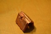
I might make a dedicated post later. The ends are just compressed (in a vise) annealed copper pipe (18mm outer, 16mm inner diameter - 0.71 inch outer, 0.63 inch inner or thereabouts). Width (and height) of one piece of the bar is 25mm (1 inch) and the bus bar handles 150A.
 
  • Like
Reactions: Dzl
I might make a dedicated post later. The ends are just compressed (in a vise) annealed copper pipe (18mm outer, 16mm inner diameter - 0.71 inch outer, 0.63 inch inner or thereabouts). Width (and height) of one piece of the bar is 25mm (1 inch) and the bus bar handles 150A.

I found in an old basement a braided cable with ends clamped like you did. I was actually quite disappointed about how bad the connection between the braided cable and the copper pipe was. Whereas the 1 m long cable had a resistance of about 0.3 mΩ, the connection between the pipe and the braid was 1-2 mΩ.

Granted that the pipe was not being pressed by anything at that time (i.e., it was not bolted), but this was a cautionary tale: in a crimped terminal the terminal is pressing very hard on the cable. Without these being bolted, due to the geometry of your (and my) system the copper pipe cannot press very hard on the braid (flat areas can't hold stress very well and get loose).
 
I'm not seeing a bad connection at all, and they don't get loose because the amount of pressure used to make them. When you cut them in half you can see a cold weld. The key is to use annealed copper though; don't use copper pipe you regularly find in the hardware store at different lengths, but use the ones that are usually sold rolled up.
 
The key is to use annealed copper though; don't use copper pipe you regularly find in the hardware store at different lengths, but use the ones that are usually sold rolled up.
I would think that the softer annealed metal would be softer and allow the middle of the crimp to open more than a harder material.
Of course, it would also form easier, and maybe create more contact with the strands.
Maybe it would be best to crimp annealed pipe then harden it with heat treatment.
 
I would think that the softer annealed metal would be softer and allow the middle of the crimp to open more than a harder material.
My understanding of the earlier pictures of construction is that the braid extends inside to the end of the copper. That way the compression of the bolt keeps the two in compression. I can't speak to the one Carlos tested.
 
My understanding of the earlier pictures of construction is that the braid extends inside to the end of the copper. That way the compression of the bolt keeps the two in compression. I can't speak to the one Carlos tested.

Yes, I presume the bolt is the thing doing the compression. I am skeptical about the large flat piece being able to maintain a compression strong enough on its own. Possible? Yes. But with any vibration/motion it will come loose unless the bolt holds it too.

Haugen, you mentioned galvanic corrosion if you use solder. Is it really that important? (in marine environs probably but if not?) Also: I know solder makes copper more brittle (that is why NASA does not solder and recommends crimping), but again this may not be an issue with a thick braided wire like this?
 
On a side note, I just published a summary of the project and rundown of all the equipment mentioned in the first post in this thread with cost and links to where I got it all from on my blog. I'll keep updating that, but all the equipment I got performs better than anticipated...
 
Haugen, you mentioned galvanic corrosion if you use solder. Is it really that important? (in marine environs probably but if not?) Also: I know solder makes copper more brittle (that is why NASA does not solder and recommends crimping), but again this may not be an issue with a thick braided wire like this?
To be clear, I misunderstood the process that was being used, and there is no soldering on the bus bars being discussed here.
On to the techie stuff...
Yes, galvanic corrosion is a real threat.
The fact that many of these systems are meant to be used in RVs, boats, and other outdoor gear and has a life expectancy measured in years and maybe decades, corrosion will definitely play a part at some point. Add dissimilar metals to the mix, and it accelerates the process.
Of course, there is maintenance and preventative measures, but I don't know if anyone plans to remove the steel bolts from their aluminum terminals to inspect them for corrosion. I wouldn't bet on it.
When it comes to solder, it is generally tin and lead which will corrode before the copper. Do a search for "F-16 fighter crash MIL-L-87177A" and let Scott Dotson teach you about how costly corrosion on electronics can be, even in a "sealed" connector.
When you talk about embrittlement, the aerospace industry is more concerned with soldering gold plated pins. This practice, not only adds additional metals to the connection for corrosion consideration, but the gold melts and combines with the solder making it brittle. There is also the topic of tin whiskers, but that doesn't really apply here.
 
Yes, galvanic corrosion is a real threat.
...
I do tend to agree with you, and understand the electrochemistry of the issue but bear in mind that Sn/Ag solder has been used for ages to solder Cu water pipes. As far as I know that has not been proven to be an issue in that context (and we are talking about installations that last many many decades if not a century!). I am just confused now :)
 
That's a good point.
I'm thinking that the big difference is that water pipes generally have no electrical current flowing through them.
I have performed tests on electronics in aluminium enclosures and seen them corrode quite readily. I'm sure you have cleaned battery terminals full of corrosion that didn't affect the bare metal next to them.
 
Back
Top